Skip to Content

Home

This is a list of articles with teasers.  The headlines below are links to the full articles.


SQ-64 Voltage Notes

skip to next article

The Korg SQ‑64 has MOD outputs for non-pitch control voltages on Channels 1–3. In its internal menus they have a voltage range and a voltage offset, but the range is labelled by positive voltage, and this is confusing because it seems by default to produce either positive or negative. Values can be programmed in 0·5 steps from 0 to 127 (MIDI-equivalent), and low values produce a negative voltage. Confusing. The manual doesn’t say anything much about it, so I tested it (with an SQ‑64 with a factory-values reset) at +5 and +10 Volts nominal maximum. (Each channels nominal range can be stepped by 0·1V from 0 to +10V.)

The results are fairly linear, with the zero-point probably supposed to be at about 63. The description should probably be ±2·5 and ±5 Volts at these settings, with 0 representing 0V and the 127 representing the maximum set; but the offset can take it up to all-positive.

So, to use the range 0 to +5V you need to either offset a lower voltage (but the maximum offset is ±1V) or use a +10V range between values 63 to 127, which for some purposes I find isn’t really fine enough.

The figures in the Appendix are those measured for Channel 1. Channels 2 and 3 were almost identical. I don’t know if the outputs can be calibrated in the device either in software or hardware, and haven’t as yet measured multiple SQ‑64s. If I get different results from another I’ll update this post.

more →


Seizure

skip to next article

Some graphics for democratic computing. The text is a line by Cory Doctorow. This page is a public draft, and may be altered or the contents moved to some other server in future.

Seize the means of Computation (with logo, colour)
Colour version. (SVG)
Seize the means of Computation (with logo, monochrome)
Monochrome version. (SVG)
Seize the means of Computation (with logo, black)
Black version. (SVG)

SD-400 Question

skip to next article

Question from ALF, 2025-09-29 13:23:46

Hey! I'm ALF, from Italy. I found your great website looking for technical info about the KORG SD-400 Signal Delay. It works but the repetisiona are quite noisy (with some "air" blended with the original sound). I think it needs some fine tuning of the clock/bias. I opened it, founding 9 trimmers! I found the ones are responsible for the feedback amount. Could you provide me any schematics or give me any advice about this process? Many thanks in advance. Ciao for now! ALF

Response:

Unfortunately I don’t have any technical information about either the SD‑200 or SD‑400 apart from the user manuals (which aren’t very detailed). It took me about ten years after first getting one to find those! And since mine have been working I haven't tried adjusting any of the trimmers. I’ve been thinking of working out the circuit some day though.


Fluids

skip to next article

I had this thought about gender-fluidity, which on consideration may illuminate the subject of gender more broadly.

Having met people who assert a variety of non-binary gender identities over the years, I’ve always been a little puzzled by the concept of fluidity, compared to gender as a reasonably constant thing. (In the absence of some major event requiring transition, though that’s more often a long-term mismatch rather than a specific event obvious to others.) I had no reason to disbelieve anyone, but I somehow didn’t get it.

I have considered that perhaps a very neutral position on the hypothetical feminine-to-masculine spectrum could produce a variable gender identity, if external influences could then overcome the neutral state. But that doesn’t clearly explain why there are people with fluid and people with consistently neutral identities. I also tend to think that masculinity-to-femininity as commonly practiced is not a single-dimensional spectrum, but rather a very approximate two-dimensional aggregate of characteristics which derive much of their imagined grouping from social influences anyway. However:

Perhaps We Flow

It occurred to me recently that another way of looking at it is that fluidity might be the norm. That is to say, that ordinary humans don’t necessarily have a real permanent sense of gender identity to begin with, rather than intermittent ones which are assumed and reified in between times. As someone once put it, I don’t wake up every morning and immediately think oh-my-god-I’m-a-woman.’

more →


Behringer 2600 Continued

skip to next article

Some more notes about the Behringer 2600.

Clocks and Transients

A point which isn’t quite clear either here or in some of the pictures of the ARPs is what the function of the S&H external clock input is. But the later (orange) ARPs clarify that in the panel layout — the jack is an input to the S&H circuit, replacing the internal clock. Consequently it can be used to time the circuit separately while the internal clock is still triggering the transient generators.

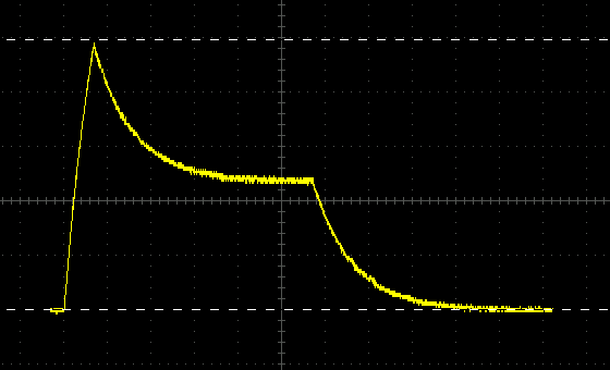
Wondering what the actual transient times were, I connected up to an oscilloscope and found that the ADSR attack is surprisingly short in proportion to the other times. This remained the case at all time settings.

Behringer 2600 ADSR curve

I measured the following maxima:

more →


Dividers

(This is the last article listed on this page.  Skip to page navigation.)

Since it’s a matter of occasional confusion, even amongst people doing synth repairs for a living, I thought I might try a simple description of how divide-down polyphony in analogue instruments works.

RCA CD4024AE 7-stage divider IC
An RCA CD4024AE 7-stage frequency divider IC.

The basis of the technology is a circuit called a frequency divider. [1] This can be done differently with digital manipulation, but a typical analogue frequency divider responds to a (significant enough) change in input voltage by waiting until a similar change recurs one or more times before changing its output. The simplest and commonest division is the one-half or first suboctave, where the count is every two cycles. (A binary divider. n.b. divider circuits are often also known as counters.)

one-half division
A simple binary divider triggering on the rising edge of an input waveform will switch its output state with every voltage rise (edge) detected. Here the falling input edges do not affect the output. Divider circuits which trigger on the falling edge can also be built.

In electronic instruments, input to dividers typically comes from an oscillator circuit. Originally, each of the notes in the top octave of divide-down instruments were generated by a separate individually tuned oscillator. The collection of oscillators this required is usually referred to as an oscillator bank.

more →


◀◀ latest posts  |  ◀ newer  |  older ▶  |  oldest posts ▶▶