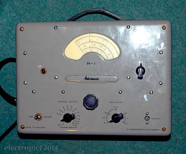
This is a rather nice thing I laid hands on this week. It’s a valve-based 15Hz–50KHz sine/square wave oscillator, probably made in 1958 [1]. It doesn’t seem to have been refurbished, but for its age and intended use it looks in good shape. Functionally? Well . . . we’ll see.
External Condition
First, power input. The cable is a flying lead with a ‘Duraplug’ shockproof BS1363 plug attached. Inside is, oh . . . oh . . . a 2-amp fuse. I haven’t had an incoming device with a 2A fuse in about 20 years. I have a sudden sense of affinity with someone, somewhere . . . somewhen. But I don’t know the actual power usage of the device yet. The fuse is old enough to be blue — it may even be original. This I think is only the second blue 2A BS1362 fuse I’ve seen. A museum piece in itself.
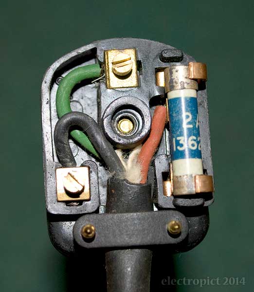
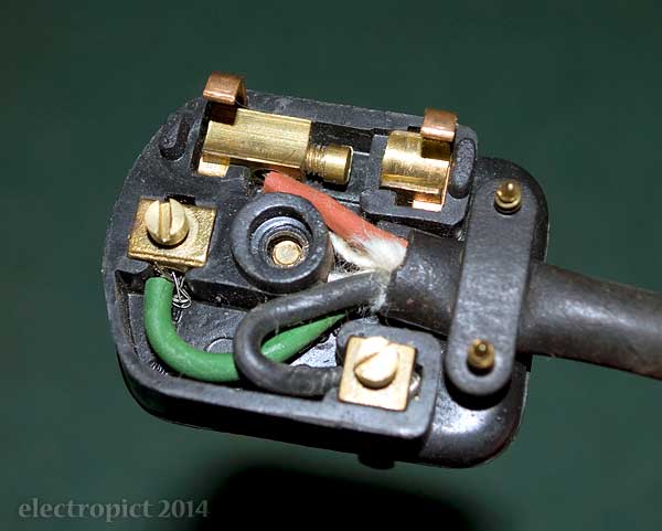
The fuse holder is quite unusual; as is the live terminal. The fuse is inserted and removed more or less sideways. It’s not held quite as solidly as it would be in some plugs, but it’s not going anywhere once the top’s screwed on. The terminal screw is inaccessible with the fuse in. I’m not sure whether this is superior to the usual arrangement. Not altogether convenient, at least. All of which is interesting, but technically this plug should no longer be used; it’s a pre-1973 type without insulating sleeves on the power pins. So . . . another museum piece? [2]
The cable is instantly dubious, as the insulator colours are old-style red/black/green — anything else would be surprising in a 1950s product. The wires are tinned-strand, and the insulators are rubber. This resembles high-temperature cable, but no; it’s just a rubber cable from before the days of PVC. And the outer sheath has cracked at the case entry point . . . so, nope, not keeping that.
On to the device itself: The controls are all very smooth and quiet in operation. The power/voltage knob is a bit loose, but we’ll see if that can be improved. The signal outlet is much like an FM aerial connector, but with one lug slot. (Just one.)
There’s a bolt sticking out at the back of the case which looks as though something should be screwed on it, locking the case in place. (According to the manual, this would have been a dome nut.) It’s at a bit of an angle though, so may have taken a knock. There’s also a removable panel on the underside which allows direct access to the power connections to the transformer. The idea seems to be that you can resolder the connections to use it on a 115V supply if you like — without having to open the whole case. That’s . . . convenient?
Opening Up
A nice thing about getting hold of old gear is that you come across approaches that have been forgotten by more recent generations of product designers. In this instance, the case. This is one of the best cases I’ve seen. Full marks for robustness, and actually for simplicity too. It took a bit of getting open (not that anyone would need to do so very often), as I wasn’t sure of the structure. Once you know it, you can open it safely and reasonably easily. But there’s no way it’s going to come open of its own accord, even if all the bolts fell out. The front panel is held on by a large steel clip on each edge, and there are no external projections to catch it on. There’s a bolt at each corner, screwed well in. You are intended to use these to push the front panel off by unscrewing. The resistance from the clips is very high, so it’s easier to lever it up incrementally as you go. (Given how solidly attached the panel is, bolting through the back seems superfluous.)
This particular H1 clearly has been opened — though everything seems in original condition — as the bolt heads have a bit of wear. It’s almost airtight too — on opening I was assailed by an unusual and unpleasant smell. I suspect someone may have had it on for testing lately, and that something in it isn’t in good shape. It’s not the smell of dust burning off valves. (The case permits little or no dust entry.) More like hot perishing rubber, perhaps overheating transformer, and maybe a hint of electrolyte. After 60 years these aren’t surprising. But I’m doubtful about powering it up any time soon.
The length of power cable inside certainly looks as though the rubber is perishing, so that confirms replacement. If there was a bit more space I’d incline to think we could have a C-14 power socket, but maybe not. (Actually there’s plenty space on the rear case, but that would prevent clean removal of the panel without disconnection. The existing cable passes through a gap in the case joint.) And there’s no internal device fuse, so we really are dependent on a low-rated plug fuse. Or maybe a C-14 socket with built-in fuse holder. If there were space. The cable is currently soldered directly to the transformer and the power switch, which is not convenient. I think I would like to replace this with a terminal block. And a fuseholder.
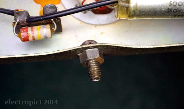
The rear bolt has definitely taken a knock at some point. The chassis is bent in and up around it.
Happily a scan of the original manual for this device has been put up at this site. [3] (They also have some other rather interesting things . . . and I haven’t seen a WebRing for a while; another technology in need of conservation?) Even more happily the manual comes with a circuit diagram, a parts list, and a basic set of service instructions. So I don’t have to spend too much time working out the details. Or, some of them. One thing that doesn’t appear either on the case or in the manual is a power consumption rating.
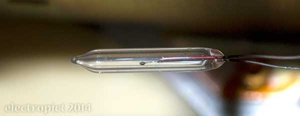
An oddity in the manual is that the components list includes an “S.T.C. thermistor A 1522/100” . . . so, what, not PTC or NTC? But STC was actually the brand name — Standard Telephones & Cables Ltd., who ceased to exist in 1991. Well there’s confusing. (The other manufacturers’ names are given after the component name.) This seems to be a type A, which would be a “bead in gas-filled glass envelope”, but I don’t see any confirmable explanation of ‘1522/100’ anywhere. It is however easy to spot, once you remove the internal shield.
Another issue from the components list is the meaning of ‘RMA 8’ or ‘RMA 9’ with regard to resistors. They might be power dissipation ratings, or maybe something else . . . A bit of a hunt on the search engines shows that I’m not alone in my ignorance of this point — but the other people I see asking about it are also trying to interpret this manual, so it may be nigh-on unique.
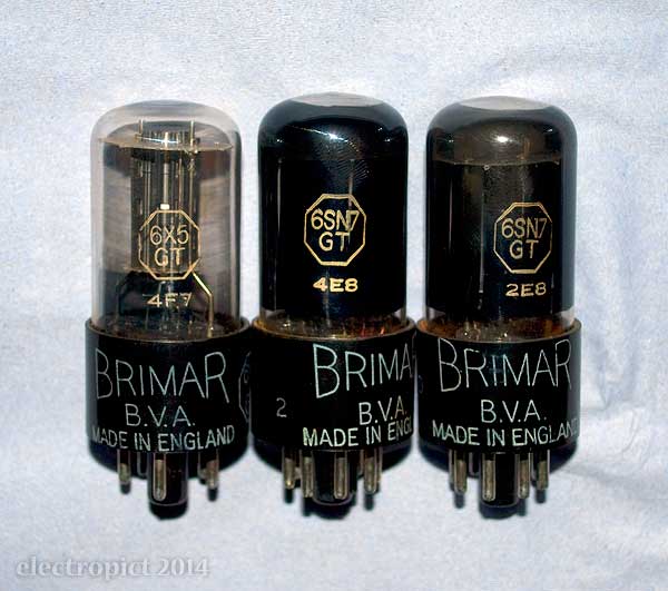
There are three valves — two 6SN7GTs (dual triodes) and one 6X5GT (rectifier). The base of the 6X5 seems a little loose, but there’s no obvious functional fault in them. (Though if they’ve had normal use, you’d expect the filaments to be at end-life.)
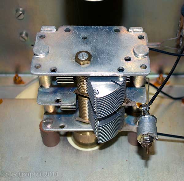
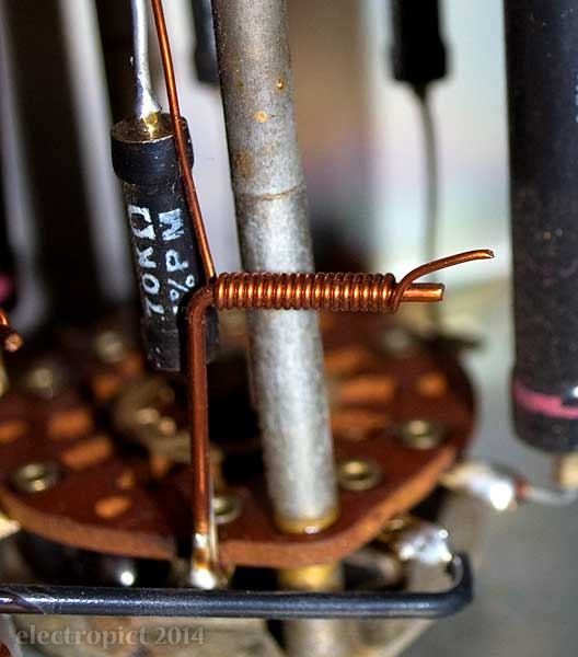
There are 17 capacitors, including a nice 2-gang variable capacitor as the tuner, and four trimmer caps, three of which are wrapped-wires (i.e. you adjust them by unwrapping a bit of wire from the core); the fourth is a small air trimmer mounted on the tuner — this had a resin locking seal, but that has mostly broken off. (I’d expect it to need calibration anyway.)
There are five electrolytics, three of which are combined in a can as a post-rectifier filter. The chances of these still being viable and within tolerance [4] after approaching 60 years is slim to non-existent, so I expect I’ll be replacing them. But the replacements will probably need to be high-temperature rated; three valve heaters in an almost-airtight case, after all . . .
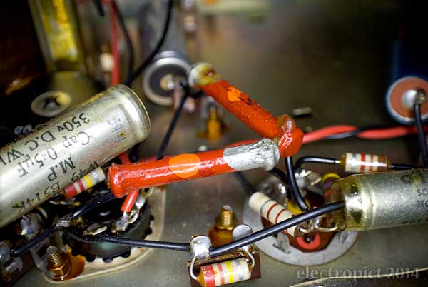
And there are some rather old kinds of resistors, including four 22KΩ ‘dogbones’ with body-end-dot marks. [5] I haven’t had anything with these marks before. Interesting that the capacitors are, in some cases at least, exhaustively marked while the resistor markings are so basic.
Being valve-based, this uses higher voltages than most devices I come across. The circuit diagram helpfully gives the transformer outputs as 6·3V and 275V, so that tells us where we’re at. The 275V supply goes to the rectifier tube, and I expect comes out at a bit higher than that . . . possibly up to 380V, according to the spec sheet . . . will need to measure. (The 6·3V supply is power for the three valve heating filaments.)
Some of the resistors look as though they’ve been running fairly hot in the past. There’s resin on them which has bubbled and dripped a bit. This does not necessarily indicate problems, but . . . the smell really isn’t right. (I actually had to leave it by an open window for a while and walk away to avoid nausea, though I expect that’s mostly the rubber.) I don’t think I’ll be switching it on for a while yet.
I’m basically going to have to put this up on a shelf for the next few weeks. Pressing matters. Something to look forward to, though.
Comment or Question about this page? write
Notes
- The seller thought it was made in 1952, but I doubt that. This model seems to have been introduced in 1951. An early advert shows that at that time a different font was used for the brand name:
 . . . although the early adverts do use the font found on this H1:
 The first is also used on older Advance products from the 1940s, so this is likely a later version of the H1, following some consolidation of the branding. Meanwhile, Advance Components originally operated out of addresses in Walthamstow (London), but this case label says Hainault — Essex, which is where the adverts place the company in 1960.
 The histories given by descendant companies APS and AEL aren’t very exact, but according to Radiomuseum.org (who seem to have the wrong date for the H1) the move to Hainault occurred in 1956. That fits, as the only dates visible in the device are the tubes’ date codes, which seem to be 1957/58. (The serial number also starts with 58 but that could be coincidence . . . ?) ↖
 - I’m not sure I want to develop a collection of plugs and fuses . . . is that just too anorakish? Is there such a thing? Am I decades too late to worry about it? I suppose I do have some interesting ones. But others have already done it rather more comprehensively than I’m likely to reach even if I tried, e.g. Oof Oud, Flameport. ↖
- Original link updated to Internet Archive 2019-09-26. ↖
- The manual doesn’t actually give tolerances for these. The can (now I’ve found the markings) is a Dubilier Drilitic CRE0667. I haven’t found any details for that specific model. ↖
- The B-E-D marking system uses the same BBROYGBVGW-GSN colour/number sequence as later markings, but uses different colour locations. The body colour is the first figure, the starting end is the second, the dot is the multiplier, and the opposite end is tolerance — gold/silver/none. The system does not allow for a third significant figure. These dogbones are red, red, orange, silver: 2, 2, 000, 10%. ↖
Article text ©2014 Electropict  .
.
Click images for individual licences.
