I tend to casually use a range of technical terms and abbreviations in this site; which may seem like a bad habit, but then, it’s my notebook. This page is for clarifications, usually where a term gets used on multiple pages. Not everything is likely to be explained here, but if there’s something really inexplicable and not covered somewhere else, ask.
- ADC and DAC
- Analogue-to-Digital Convertor and Digital-to-Analogue Convertor
- An ADC is a device which converts an input signal to a representation as digital data which can then be stored and manipulated as data rather than using the original signal. Technically it is not necessary that the input signal be analogue, as any input will be treated identically, but most digital signals would not be very useful after conversion as they are a code.
- A DAC provides the opposite function, converting input code stream to an output signal. The output signal will be stepped (rather than digital) at the DAC’s resolution in both time and amplitude.
- Resolution and other qualities of ADCs and DACs have a significant effect on the sound produced by a digital or hybrid audio system.
- BB or BBD
- Bucket-Brigade (Device)
- A type of delay circuit based on the successive storage of signal levels in a series of capacitors. Bucket Brigade Devices are implemented as microchips, and were used extensively in music in the 1970s and 1980s prior to the advent of cheap ‘digital’ delay systems.
- The operation of a BBD is to take a sequence of instantaneous measurements of signal level, hold them, and pass them through the chain until the output is reached. Because there is a unit of hold time involved, you occasionally run across an argument that BBDs are digital devices, but this ignores two points: firstly that even if the time unit were digital, the charge levels stored are not, and secondly that the time unit is usually (every case I’m aware of), continuously variable, using a voltage-controlled clock. It is more accurate to say that it uses discrete rather than digital timing units. (As distinct from some electromechanical delays which use bodies such as springs to continuously regenerate the signal, no units involved.) [1]
- B-E-D or B-E-S
- Body-End-Dot (or -Stripe)
- A colour code method used on some cylindrical resistors and capacitors in the mid-20th Century. The body colour is the first significant figure, the end colour (the end with no tolerance stripe) is the second, and a dot or stripe of colour is the multiplier. Tolerance end colours were either gold, silver or none. The implementation may not have been consistent between manufacturers.
- CCR
- Carbon Composition Resistor
- Carbon Composition is a sort of graphite paste which was (and still is for specialist purposes) used to make resistors. It attracts moisture over time if not kept warm, producing changes in resistance. Most ordinary CCRs seem to rise in resistance, eventually exceeding tolerance. This can to some extent be reversed by drying out in warm conditions, and restoration by recoating with a moisture barrier e.g. shellac. The paste can also be permanently damaged by excess heat, e.g. in soldering. CCRs tend to produce signal noise, so it may not be worth retaining them in old circuits; on the other hand they handle high voltages particularly well so are still used in some specialist equipment.
- A variant is the Ceramic-Cased CCR (CCCCR), in which the paste is injected into a ceramic tube and capped off with resin at both ends. This is significantly more resistant to moisture ingress; they tend to remain in-tolerance for longer.
- Some CCRs and CCCCRs were made using a stabilised paste; these frequently remain at or close to their original values after thirty or forty years; as good or better than Carbon-Film resistors of the same age.
- Both types are found very widely in musical equipment from the 1960s and into the 1970s, particularly valve equipment.
- TOG
- Top Octave Generator

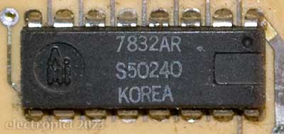
- In typical use, a type of integrated circuit (or pair thereof) developed in the early 1970s to produce a full octave of 12 (or 13) pitches by division of an initial input frequency, closely approximating 12-Equal Temperament proportions. Like earlier frequency-divider instruments, further octaves are produced by division of this ‘top octave’ by divider circuitry. TOGs are most often found with integrated circuit dividers, which were developed around the same time. This allows all notes of an instrument to be permanently fixed in relation to each other, or modulated or pitch-bent in step with each other, which was less simple with earlier tuning methods.
- The earlier method used to produce the top octave in frequency-divider instruments, a group of 12 individual oscillators, can also be described as a top-octave generator, and if it’s built as a single unit that’s accurate, but it’s more commonly called an oscillator bank. Once the TOG chips had been developed, they rapidly became cheaper as well as physically smaller than an oscillator bank. However, they do have the slight disadvantage of not allowing varying temperaments. [2]
- semimodular and modular
- While the definition of ‘semimodular’ is debatable, for present purposes it means an instrument with a default (‘normalised’) signal route between ‘modules’ which also allows the route to be changed at will. This can be achieved by switching or patching with external accessories such as cables or patch pins. This is distinct from a fully modular instrument in which there is no default route, which requires patching to produce an output signal, and distinct from a module, which (loosely speaking) might be capable of generating an audio (or other) signal but which requires external control to vary it, if variation is required. (But there are modules which incorporate their own controls and can automatically generate complex control signals for themselves.)
Comment or Question about this page? write
Notes
Conversely, a ‘digital’ delay measures signal levels with an ADC with digital timing (i.e. using a clock based on a specified number of pulses rather than a continuously variable period) and stores the resulting data in memory, processes the data rather than the signal, then reconverts it to a signal with a DAC for output.
As with many other devices since the 1960s, the word ‘digital’ has been rather haphazardly applied to delay units for marketing purposes. Most early delay units which used digital signal memory still retained the analogue filters and modulators of older units. These may be best classified as hybrid delays. Ironically, the high regard some of them are held in on grounds of sound quality may be more to do with the tonal effects of the analogue filters they use than that they use digital memory, or their sampling resolution. ↖
- There is no reason why other tuning schemes than 12-ET could not be approximated just as accurately and consistently with a TOG with different ratios, but it probably wouldn’t be commercially viable and I haven’t heard of one. You could probably program a PIC for it, or to switch between temperaments? ↖
Article text ©2022–2024 Electropict  .
.
Click images for individual licences.
