The Stringvox (without a space) is Hohner’s rebadging of the ELEX K2 electronic piano/string machine. There were three versions sold by Hohner, the original ‘silvertop’ (K2r1 by my nomenclature) which seems to have begun production in 1975, the slightly changed rev.2, and the ‘blacktop’ (K2r3) from 1979. All are in effect built into their own flightcases with lift-off lids, but the r3 case shape is different. (For more information on the series see A Spotter’s Guide to HIPs and Strings.)
I have only been able to find out a little about these previously; in particular I have little information about the interior. [1] Recently an r3 came up for repair, so let’s have a look.
Facticules:
- Keys: 61 F–F, 23·5mm pitch
- Voices: Bass, Piano, Harpsichord, Cello, Strings.*
- Weight: 34·3Kg (including 7·5Kg lid, 26·8Kg without) †
- Dimensions: W 1140mm × D 405mm × H 158mm / 206mm (inc. lid and feet) †
- Power: 240VAC, 10W †
- Outputs: General, Bass, Piano/Harpsichord (all TS)
- Inputs: Piano Sustain pedal (TS), General Volume pedal (DIN-5-180°), Bass Pedalboard (DIN 41622), AC Mains (C-14)
- * Cello and Strings voices have a chorus effect. This is a fairly typical BBD string-ensemble effect but as there’s a different thing called Ensemble here I’ll call it chorus.
- † These figures would not apply to earlier K2 revisions.
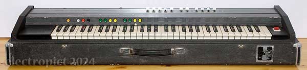
This Stringvox (K2r3)
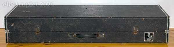
This was sold as in need of repair, with the main known problem being that the plug side of the appliance fuseholder is missing. [IN1] Other than that, it came with a stand but without its case-attachment bolts. [IN2] (This is one of those instruments which can rotate on its stand to get a better playing angle, though the stand doesn’t adjust vertically so that’s of limited use.) It could of course do with a clean up and maybe some repair of the vinyl. [IN3] There’s a bit of rust on the hinges. [IN4] As is quite common with these keyboards, the plastic edging on the ports hole on the rear is incomplete. (This is what you get when you put the ports on the outside of the flightcase.) [IN5] It hasn’t been used for some time, perhaps several years, so given its age we can expect some capacitor issues. [IN6] However, under the cover it’s in better condition than most I’ve seen. It would originally have come with sustain and volume pedals and a music stand but these have all gone. It has a socket for a bass pedal board but they were optional extras, and since I’ve never seen Hohner or ELEX bass pedals, they probably weren’t popular.
Condition
On arrival . . . it’s heavy! This is certainly the heaviest single-manual keyboard I’ve ever handled. Its lid is slightly misplaced as if something has bent but we’ll see. Some of the keys have slight dents and scratches but they all operate well and the bushes don’t seem to have hardened. This one originally had two bass-range marker tabs but one has gone. [IN7: Consider missing tab replacement.] There’s a vaguely mushroomy smell, but I understand this has been sitting doing nothing for about ten years so not surprising. The switches all operate without too much stickiness and only two of the faders are a little sticky. [IN8: Clean faders.] There’s a power cable under the lid (nice plug, 5A cable, 13A fuse . . . replaced with 5A for now), and what looks like part of the handle in the packaging. I reattached that before going any further. I can’t do much else without replacing the fuseholder, so time to get it open.
The top panel has six rather long screws (the rear left hole has a stripped thread), and then has to be pulled up at the back and forward over the pushbuttons. It’s easiest to do this with all faders forward and as many switches in as possible, but it’s still exceptionally difficult. The slider caps have to be removed. The panel is attached by an earthing strap to one of the music stand sockets, which has a splash of threadlock on it, but it looks like someone’s been here before as the bolt has the opposite splash. So it should be fairly easy to remove but I’m not sure if it’s necessary yet.
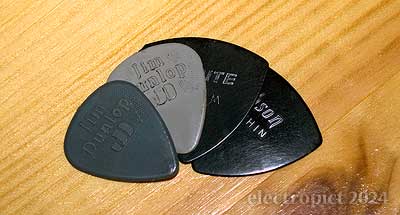
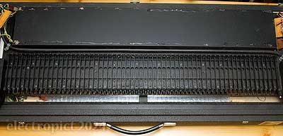
Inside, someone’s helpfully left me an old Jim Dunlop plectrum. And there’s some fluff but apart from the faders it’s otherwise clean. The switches and faders are on their own daughterboards (ELEX K2-110 & K2-13), together with two smaller boards (ELEX K2-9 & K2-10) which might be filters, on a large board (ELEX K2-14) running the length of the keys, which acts as a backpane. Extensive use of pin connectors. It’s screwed through a pair of chipboard strips into a metal plate which is welded on chassis bars.
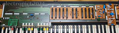
K2-110 is mounted slightly forward of the K2-14 on a steel extension, which covers some of the key hinges and return springs, so that’ll need removing later. The leftmost switch is mounted on a metal extension which has a hole to allow it to be bolted into a bracket which itself is bolted through the board, and the plywood strip under it has a notch for the bolt; but if the extension-to-bracket bolt was ever there, it’s gone. It may not have been, as it still resists pressing; there’s no pull action.
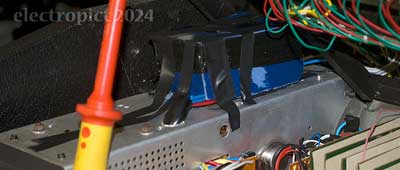
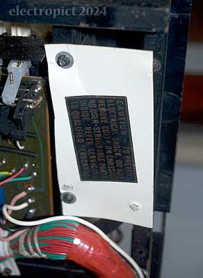
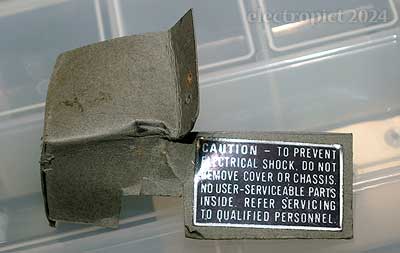
The power supply — which as in the earlier K2s and K3s is in a metal enclosure/heatsink which I’d expect is a significant contributor to the weight — has one of these ELEX cardboard boxes taped on, presumably over some exposed mains power. The tape doesn’t look original. And there’s another cover at the back over the fuseholder and power input, so I’ll need to do a bit more dismantling.
First the keyboard has to come up. It’s currently held down by one M4×65mm slot-head bolt from the underside, but there should be two. [IN9: Replace missing keydeck bolt.] In this model, there’s a single chassis which hinges up along with the control and filter boards. Something isn’t fitting right. The front of the chassis is scraping loudly on something, probably the plastic dust shield. The chassis doesn’t hinge up past about 70°, but I’m not sure why. Is there something blocking it? Well, in the interim it should be possible to work on it propped up. Under the keybed everything looks quite clean too.
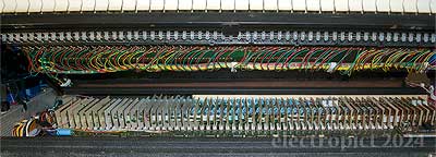
As with the early K1s, the power input and PSU are at the opposite end of the case from the mains switch, so there’s a set of mains-voltage wires running the length of the keybed, tucked behind the keybed. A rather inexplicable design choice. [2]
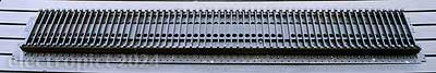
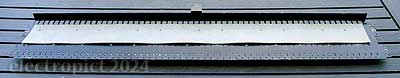
There are three sets of contact springs here — one for the bass range only — and four contact bars, one for the bass range, one which I assume is for strings (which is divided between E2 and F3), and a pair which I assume is a contact bar and a timing bar for pianos with touch sensitivity as on the K1s. Each set of springs has a plastic retaining bar; the one for the bass range has fallen out, but it should clip back in. [IN10: Reinsert retaining bar.]
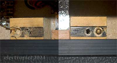
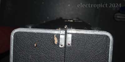
The keybed front support blocks should have brass locating pins but the left-hand one has torn out. This is also where the bolt’s missing. [IN11: Replace locating pin.]
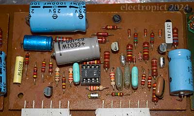
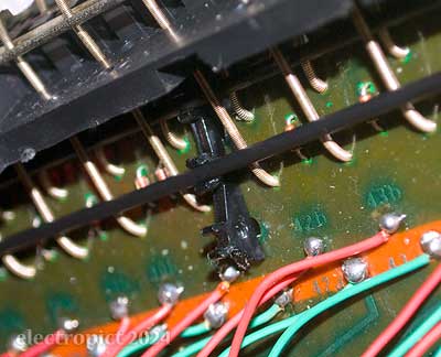
The main board (ELEX K2-2) has nine divider chips, 1978 TMS3848s and a socket for a top oscillator board, the same ELEX OS-5 as in the K1r5 and K1r6, with an MK50240 TOG chip. Each divider has a small yellow Plessey PET capacitor beside it which I assume is decoupling. One of them seems to have been damaged. Close examination shows it has a couple of holes left by a soldering iron, with solder melted in; which I imagine isn’t helping. I’ll replace that before powering up. [IN12]
Unsurprisingly the ensemble effect is different from the r2 and K4r2 pictures I’ve seen. Instead of metal-cased chips, here we have DIP-8 TCA350Zs providing the delay — to be expected for 1979. But unexpectedly, where the K2r1 and K4r2 String-Orchestras use two of them, here we have three identical delay boards (ELEX K2-20-2), which should result in a slightly more complex sound.
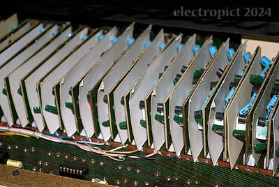
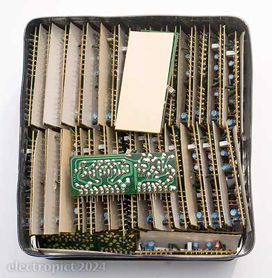
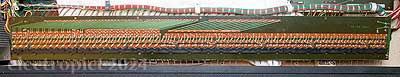
The ensemble boards are three out of the six daughterboards (the other three are numbered ELEX K2-6, K2-7 and M174) on another backpane (M175) below the keys. Most connections here seem to be socketed, which makes maintenance significantly easier. Especially when you just want to get at the fuseholder. In particular, unlike the roughly-contemporary K1r6, the envelope daughterboards (ELEX K2-1) are in sockets, and are insulated from each other with loose cards.
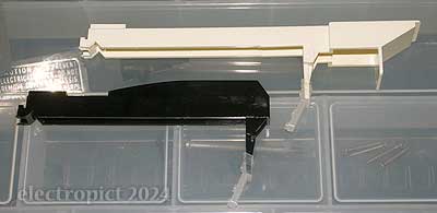
I might have thought these cards were non-original but they seem to be the same as is used as an insulator (with what seems to be an original warning label) on the underside of the power switch.
The K2-1s are labelled in felt tip, from the left, 4×A, 3×B–I, 3×L–P, 3×R–U, 3×W, 3×Z. I’m not sure what the rationale is for the letter choice, but each of the twenty groups seem to have different components. These boards are more complex than the envelopes found in the pianos as they do three different envelopes, one for pianos, probably including bass, one for Cello, and one for Strings; all three have damping/decay options. So I assume that the discharge times are different for each of these groups. That’s a bit more detailed than in the K1s. (Later: But it turns out that the pianos here do not have timing component variations over the length of the keyboard, which the K1s did — three variations if I recall — so less detailed there.) These boards have a section which is closely similar to the K1r6’s envelope boards, though those are presumably the derivative design. So the other side (right components side) is presumably the strings sounds. (Later: The strings side seems to have been re-used for the K4.)
(The K2-2 board is actually labelled with these group letters in copper by each socket pair, as a suffix to the individual number, from 1A to 61Z.)
Power
The primary concern at this point is the condition of the power supply after ten years. Not going to do anything till that’s checked. Getting it out required loosening the K2-2 board and taking out the lowest ten envelope daughterboards to get a screwdriver in. (In doing so I noticed that the cards may be there as much to act as slide-sheets as insulation, since removal takes a bit of force and component damage might be possible, especially if removing one between two others.) K2-2 would need to come out along with the keybed/contacts board (K2-3) as the wiring between them isn’t socketed. By removing the daughterboards I was able to avoid even untying the wiring harness for now.
Power outputs are from a 9-pin connector board and a socket on another board screwed to the outside of the PSU.
Most of the interior screws here have the same flanged 4mmAF hex/slot heads that ELEX use on most of these Kn keyboards. (In several different sizes without clear differentiation of use. A sorting tray and notepad are highly advisable if tackling one of these. [3]) One of the screws on the PSU was only halfway in, implying that someone’s been here before. In the process of disconnecting what sockets I could, I found another two plectrums (Dunlop and Shute), a blown fuse, a metal ring that looks like part of a broken ¼″ jack, and a large star washer. Doing quite well for plectrums out of this . . .
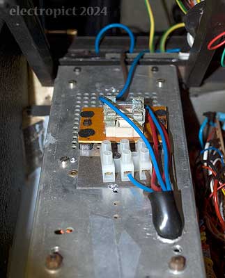
Before removing the PSU I untaped the cardboard box. It would originally have had two screws but they had torn through and are gone. Unsurprisingly there’s a mains connection (from the power switch) and a couple of fuses underneath. (For reference I’m numbering them F1 and F2, back to front.) There’s a fair bit of corrosion on one of the fuses and both holders. [IN13: Clean and assess fuseholder corrosion.]
I’ll make a perspex cover for this to keep the damp off in future. [4] I also unscrewed the card cover over the mains power input and fuseholder (though it didn’t come out completely till later); it’s in questionable condition. [IN14: Consider insulating cover replacement.] There’s an earthing lug at the front right corner of the PSU with a couple of wires to it, which is easier to remove with the PSU half-out.
Last thing for removal was to disconnect the mains power at the terminals on top. But with the screws loose they didn’t want to come out. They were trapped under the fuseholder board (M282). I see this as A BAD THING — thin-sheathed 240V wires compressed under a through-hole circuit board onto a metal case — but once the board was loosened the sheaths didn’t seem to be damaged. Still, I’ll want to do something about it when reassembling. [IN15: Ensure safe routing of switch to PSU terminal mains wiring.]
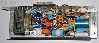
The PSU is enclosed at either end by plywood blocks which the heatsink is screwed into, with 4 × 21mm hex/slot screws on top and one and two 16mm (shorter to avoid the top screws) on the side. (I think there should have been another holding the fuseholder insulating cover in place.) The ends and the case under it have been painted grey. And there’s another star washer, which may have originally been on the earthing lug mentioned, not sure. The bulk of the PSU weight is the transformer, and in total it’s only 1·5Kg, so that’s not it.
Inside . . . there’s a 20mm fuseholder with a bit of busbar soldered into it! All the other components look original . . . is that what someone got in here for? Well, it’s possible that this board was originally used in an earlier model in a more accessible position, and this fuse is now provided by one of the top ones, for maintenance convenience. So work out the circuit. I notice as well that there’s a power resistor clipped to the case with one of those plastic wire clips. Scarcely ideal . . . And there’s a trimmer — which isn’t accessible with the instrument powered up and PSU in place. Which rather contradicts the idea of convenient maintenance.
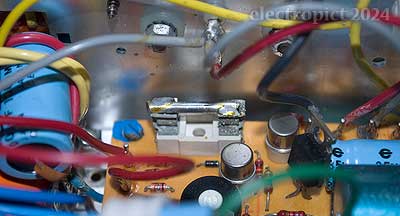
In fact, so distracted was I by the idea of soldering a bit of busbar into a fuseholder that . . . I didn’t notice there’s two of them. Which I suppose makes it more likely that these are original. 
This PSU is unusual for 1979 in that it is just a raw linear PSU, not based on voltage regulator ICs. Presumably ELEX either thought the ICs weren’t good enough for their sort-of flagship product, or it didn’t seem worth paying for a redesign for a relatively low-volume product. [5] This is a 10W, not the earlier 25W or 16W versions. (Later: According to the rating on the plate on the back it is. But this is probably not accurate. See page 3.)
Two of the electrolytic capacitors are connected using a tag strip, which also serves as the connection point for the ground outputs. Unusually, there are no non-electrolytic capacitors in this unit. Looking more closely, there could be another reason why someone’s been in here — one of the transistors, a TIP41A, is dated 1982; and in fact, the TO-3, a 2N3055, is dated 1981. (That replacement might be where the insulating bush came from.) (Later: The soldering on the TIP41A does seem to have been done later, by hand, than the rest of the board, which I think is bath or wave soldered.) There’s also an odd detail, that while the standoff posts under the circuit board are plain with only bolts on the outside, there are marks on the aluminium from star washers on all of their holes. And — while I don’t get why you’d bypass them with busbar rather than just leave the fuseholders out and use jumpers — working through the circuit, these fuse positions are the direct outputs of the bridges. And the box-top fuses are between the transformer and the bridges instead, so we’re covered. The fuses need removal and clean-up.
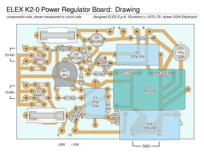
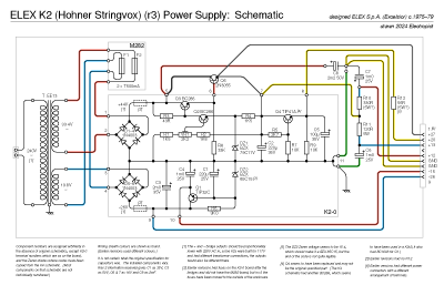
(n.b. all drawings in these articles have been reworked multiple times since the original notes were written. Many of them are a bit complex for viewing as pictures; it is recommended to view the PDF version.)
I can’t read the part numbers on two of the diodes, but DZ2 behaves like a Zener, and the DZ1 is a BZX-something. (Later: When replacing capacitors I tried to get a closer look at DZ2, took it out and still couldn’t really read it though it seems to be a 85C-something. Its Zener voltage measured at around 15·4 which means it’s probably BZX 85C15. Later still: I also took DZ1 out and got the code, now on the diagram. Yet later: I confirmed the Zener voltages from the ELEX K4 schematic.) Anyhow, capacitor testing.
(See detailed results in Appendix: Capacitor Tests)
For something that’s past 40 and may have spent ten years unused the results are pretty impressive. Almost everything is just a little above its target rating and DFs are all low. C1 may be high enough to be suspect but I’m happy to do a power test with it on this basis and see what happens as it wakes up. One thing I will do, though, is replace the thermal transfer paste between two of the power resistors and the case, which has dried up and flaked.
[IN13:] Getting them out, the fuses both seem good internally. The corroded one is a “FUSIT” with its ratings (T500mA) printed on the glass, which is good, because the ends are chrome-plated and the chrome has flaked, with copper corrosion underneath. Replaced. The other is in good shape, also T500mA, which can be read on the cap, along with a kitemark and a logo I don’t recognise. The fuseholders are also a bit degraded but a bit of work with a wire brush helps. I might just replace them anyway as they’re not going to get any better with the years to come.
Power Tests
I left it on for a while at low-voltage AC input to see what happens. Measuring the outputs like this results aren’t encouraging as there don’t seem to be many live voltages, but that might be that we’re not getting past the turn-on voltages in some places. Most of the components are warming up a degree or two above ambient but nothing dramatic. C8 is more like two degrees above.
After about three hours all told, I switched off and left it overnight. Late the following morning I tested again. Second round tests show hardly any difference, except C8, where the DF seems to have risen significantly while the capacitance remains about the same; a highly unlikely result, but maybe compatible with its slightly elevated temperature. I’d guess that it may be dried out a bit. But on to full-voltage testing.
The power outputs don’t make much sense. In order, the powers (with no load) seem to be roughly:
| pin | 1 | 2 | 3 | 5 | 8 | 9 |
|---|---|---|---|---|---|---|
| V | +26·4 | +20·2 | +26·5 | +26·5 | −0·5 | −0·3 |
The transformer outputs are 33·4V and 19·96V. And the bridge outs are 44·1V and 0·5V. But I note that the pin 9 voltage is rising slightly, now at −0·45V, so there’s probably a capacitor affecting things there.
This PSU is unusually quiet, even under mains voltage. It is audible, but only just. Whether that’ll last under load conditions I’m not sure.
After another continuous half hour under mains power, the pin 8 & 9 voltages have risen to around −4·5. Temperatures are a bit higher but still nothing significant, with C2 the warmest component at around 24°. Pins 1, 3 & 5 are stable at +26·5V.
After another hour and leaving things overnight, there’s not much change in the capacitors; mostly a little improvement, but I don’t think we’re getting much further. It seems likely that the three +26·5 outputs are as intended, just that with no load pins 3 & 5 — which are dropped voltages from the pin 1 supply (which is direct off the 2N3055) — will have equalised over their power resistors. Whereas pin 2 also runs off that supply, but goes through its own regulation circuit, and is fairly accurate to +20V, for what it’s worth. I can’t predict what the pin 3&5 voltages should be, but the resistors are in tolerance so it shouldn’t be a problem.
I checked the trimmer; it can vary the pin 1 output from 18·5–41·6V. Quite a range, and gives us no real clue about what it should be. I haven’t found any definite information about the TMS3848s, but they probably use at least 15V. The output wires from pin 1 are three thin orange-sheathed ones, which go to the M174, the K2-14, and the pedalboard socket. So I think I’ll leave the trimmer where it was for now and reconstruct everything. May have to take the PSU out again to tweak the trimmer. Convenience and all that . . .
After a few days doing other things, I checked the voltages again. This time pin 9 started low but slowly rose to around −15·6V, over about 12 minutes. This may indicate that C3 is struggling; which would be consistent with its rising DF. Pin 8 got to about −14·6V. Pin 1 rises faster to about +26·5V.
So I tried replacing C3; it made little difference. The next candidate would be C1, which of course I’ve already had doubts about as it’s substantially higher than the 220µ target. With this replaced, the rise in voltage is significantly faster, less than half the time. That may just be because the replacement is lower-capacitance, though. Next, replace C4. Little further difference. Pin 9 voltage is now rising to about 15·1–15·2V over about 6 minutes and staying stable in that range over half an hour. I doubt it’s going to get any better.
(Later: It turned out there were reasons for the slow start, and with those resolved, it’s no longer an issue.)
Structure and Destructuring
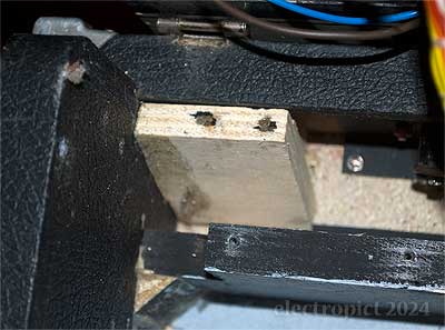
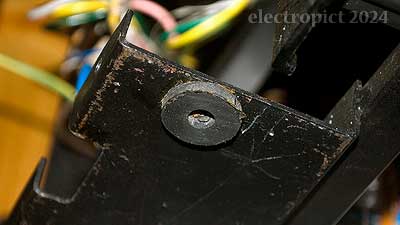
Once I had the PSU out I had a closer look at the keybed hinge, and indeed, its left end support has broken off the case. [IN16] It doesn’t look like it was especially strong to begin with . . . So complete dismantling will be required, but it should end up with everything that bit straighter.
An odd detail is that there’s a hole through the left end of the keybed chassis, with a rubber washer adhering over it. (It fell off later and I reglued it.) It looks as though this would have held a screw into the case. But there’s no equivalent on the right end. Maybe the extra support was considered necessary here because there is no hinge over the ports panel? (Later: Probably not. It may have an actual function.) There is no screw, but it looks as though the keydeck is currently a little too far forward to match the hole, so that’s probably been left out at some point.
Saying dismantling is a lot easier than doing though. I came to some conclusions:
- The top panel is attached to the keybed rather than the case, but prevents it opening anyway. The reason being that the axis of the hinges is forward of the edge of the panel, so the back of the panel has to go downwards, and can’t. Even with the panel off the controls deck projects behind the hinge axis and limits the angle to which the keydeck can be opened, rather pointlessly.
- To remove the keydeck requires all the interior wire harnesses to be untied, although the connector to the front boards can just be disconnected. Irritatingly, even with the other sockets disconnected there are a couple of soldered-in wires looped in and keeping everything else together.
- Even so, the keybed assembly can only be flipped back behind the case, and needs some support at about its original height do so safely, with K2-2 resting on it. Even then, there are wires to the ports panel which can end up under some strain. To completely separate the case without desoldering, the ports panel has to be removed.
- K2-2 is a bit long and flexible to be moved around with the weight of the envelope boards in, so I’ve removed the rest.
This isn’t the best design for maintenance. Also some sharp edges somewhere, which haven’t quite drawn blood yet at the time of writing but the lesions are obvious. Another problem is that the cable clips, which seem designed to look like plastic coated wire (which is flexible enough to open up to remove), aren’t (and aren’t). They’re solid plastic mouldings and either started or have become brittle, so I need to replace the first one I tried. [IN17]
All of which done, I can see that the damage to the hinge support is not new, as there’s some fluff build-up where the block would originally have been.
And another (Gibson) plectrum. Odd place to store them, but fine.
Looking at the ports (I/O) panel, although the volume socket is DIN-5, only three of the pins plus the skirt are present and wired, so the plug could be DIN-3.
The panel screws (16mm) are quite tight compared to the others. With it out, we finally have separation. And a few more things turned up — [IN11:] the missing locating pin, some more hex/slot screws, another possible ring from a ¼″ jack, a small bent brass screw which doesn’t look like it came from this at all, and a transistor screw insulating bush. And it looks like two of the I/O jacks aren’t original. In fact one of them is loose; it needed packing out with another washer.
With everything apart and vacuumed out I can check the weight of the base — 11·1Kg. Which combined with the power supply means the panels, keydeck, and boards must total about 14·2Kg.
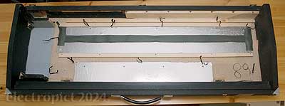
Like the other Kns the case construction is pretty cheap, vinyl on chipboard, with light plywood for most of the internal support structures, and rough pine for the keybed support blocks. Foil is used to shield K2-2 and M175, with a rather delicate strip of hardboard clamping the front edge of K2-2 down. It’s very solid all the same, probably in part because to be used with its stand the ends have to be heavy-duty enough to support the rest. That probably adds a couple of kilos.
(Later:) I also noticed in some online photography that where I have wire cable ties keeping the wiring loom down, the earlier K2r1 Silvertop String-Orchestra had P-clips, which I think should make it possible to loosen the wiring and remove the K2-2 board without removing K2-1 boards to get at the ties; which seems like a better approach. But I’m not sure what’s happening beside the I/O panel, where I have two cable ties. I’ve noticed it’s possible for some of the contact wires to get trapped under the K2-2 board when reseating it.
Cleaning
The keys needed removing and cleaning, of course, and that means removing the switch board (K2-110). While I’m at it I want to know what condition the whole of the chassis is in, so the other top boards can come off too. The switch board support is screwed into the main chassis with three 9mm screws. The K2-14 is screwed into strips of chipboard rather than plywood; they were glued to the plate under them but have come loose. Just in case, with the boards off I tried hinging the deck up again. Still limited to about 75°. It’s the edge of the top plate that’s stopping it. Not ideal. In particular, having to take the top panel off to get at the fuses is a bit much.
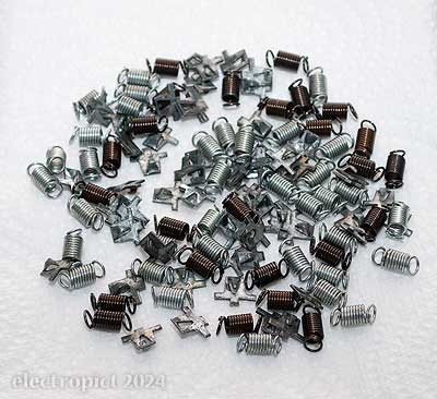
The keys are the same as on the K1r5&6, all plastic, with a hook at the rear end supporting a galvanised steel clip each, on which the return spring hooks. They have three-way removable springholders. They come off easily enough, and reveal a quite grimy, gritty, and dog-hairy keybed. This is a complex one, composed of plastic mouldings riveted to a steel plate, which is screwed to the chassis.
It also supports the contact board assembly, which is quite like that on the K1s . . . awkward. But eventually it comes off. The spring-retaining bars (two full length) are mounted on plastic clips.
It turns out that the treble-end clip is a bit broken. They’re plastic-welded on the other side, but this has cracked. (I’ve put it back in with glue and a pad above the board for it to stick to.) Once the contact board is unscrewed the keybed can be separated for cleaning.
The keybed can’t be immersed, so I’ll need to settle for airblasting and wiping it with cotton buds. The chassis also needs a clean, but a wipe will do. It’ll have to as some of the wires are looped through it. Some paint came off the keybed while airblasting.
The keybed underside has a piece of card to insulate the contacts board, which I had thought was glued on, as it is elsewhere, but it came off after this shot. It was only held on by having been screwed through.
The black keys cleaned up with a soak in warm water, but the whites had a bit more grime around the lower front; probably tobacco tar. That didn’t come off after a second soak in hot water, so I wiped them with an alcohol-based cleaner.
The springs and mounting plates cleaned up nicely left in a small jar of penetrating oil for a couple of days.
None of the key bushes were hard or cracked so I just relubricated them. The keys go back in easily; but this may be the most or at least second most difficult keyboard I’ve ever put the contacts back in. Having done it once, I conclude that it’s probably best to remove the spring holders from the keys and fit them on the springs before putting the keys in. (At this point I’m not sure how much easier that would be, but it has less potential for damage.) And the retaining bars should be removed for the duration of the process.
The case cleaned up reasonably well. There are some red paint marks on the lid, which comes off with isopropanol. There are several rips, holes and worn spots in the tolex to be repaired. I’ll do that later.
Looking at the hinges, I’m not sure they were really designed to be used in this way; if they were a bit higher on the case they wouldn’t pull the lid back so much. On the other hand they might not have enough depth of wood to avoid breaking out.
This has turned into a long article so I’ll have a break here. In part two I’ll try to put it all back together. Will I succeed . . . ?
| active | IN1 | replace appliance fuseholder |
|---|---|---|
| IN2 | replace instrument stand bolts | |
| IN3 | clean & repair exterior vinyl | |
| IN4 | derust hinges | |
| IN5 | replace plastic edging round ports hole (or make consistent somehow) | |
| IN6 | check electrolytic capacitors | |
| IN7 | consider missing marker tab replacement | |
| IN8 | clean faders | |
| IN9 | replace keydeck bolt | |
| IN10 | reinsert contact spring retaining bar | |
| IN11 | refit keydeck locating pin | |
| IN12 | replace damaged capacitor on main board | |
| IN13 | replace M282 fuseholders | |
| IN14 | consider insulating cover replacement | |
| IN15 | ensure safety of mains wiring to PSU | |
| IN16 | refit broken-off left keydeck support | |
| IN17 | replace broken wire clip |
This post has been updated in Hohner Stringvox repair notes (part 2).
Comment or Question about this page? write
Notes
- Information available about K2s generally, and specifically about the K2 String-Orchestras, has been very limited prior to 2023, but with the publication of The silvertop String-Orchestra photographs at sequencer.de in May we have an evidence attractor effect where there is suddenly better information about that specific version than about any other K2. This repair article will have a similar but balancing effect for r3, so now it’s the r2 that has the least evidence available, which previously had the largest number of photographs, but all of them exterior. If we get a look at the insides of one of the wooden K2 String-Orchestras or some earlier K2 silvertops some day, there may still be some surprises in store. (At the time of writing, not counting original marketing materials, I’ve seen photography of one ELEX and three Hohner K2r1s, three wooden String-Orchestras (expected to be r1s), one r1 and one r2 silvertop String-Orchestra (and possibly a second in a single unclear older photograph), and one ELEX, one Excelsior, and two Hohner blacktop r3s. Sixteen known survivors in the last decade.) ↖
- It’s not as if they didn’t have an otherwise empty panel to put the switch on directly above the PSU. And why they persisted with that here when they changed it in the contemporary redesign K4r3 and K1r6, I have no idea. ↖
- I came to think that the screws as I found them were not all in their original positions. I eventually found several loose screws too, and ended up with exactly the number required to fill all the holes I found, but I couldn’t consistently match sizes to positions, and abandoned the screws diagram I was working on. ↖
- All the ELEXes I’ve seen with these card covers have had corrosion happening. That might be to do with the plated metal used, but I suspect it’s at least partly that the card holds moisture if not kept in warm and dry conditions. I imagine this is less of an issue in Italy than in Scotland. ↖
- The K1r1 and possibly the K1r2 had a simpler transistor supply, but by the time of the K1r5 it had been redesigned to use a voltage regulator. I’ve only seen a picture of one other K2 PSU; the silvertop String-Orchestra had a TO-3 transistor on top, but here it’s on the side (like the one K3 PSU I’ve seen), and the power outputs appear to be bundled with the inputs on top, with no side connector. ↖
Article text ©2024 Electropict  .
.
Click images for individual licences.