Finishing the repairs, reassembling the keyboard, tidying up some remaining issues, and giving the results a listen.
Some More Drawings
Before tackling the Bass voice, since I want to know what’s happening with the filter boards, I did some more drawings.
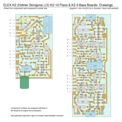
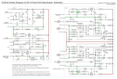
The two sides of the K2-9 board are identical. I had expected them to be producing different tones, but they’re the bass and treble/all sections, each producing a piano and harpsichord. [IN22:] I notice that Sebastian’s pictures include a seventeenth capacitor on K2-10 which I don’t have, though I do have pads and board holes for it. C17 seems to be part of the audio path; I don’t see how it could be working without it. Looking at the board again, the pads where it would be have solder blobs. No other empty pads have solder on either the K2-10 or K2-9, so I suspect that there was a capacitor and it’s been removed. Probably for a reason. I’ll get back to that later.
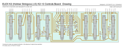
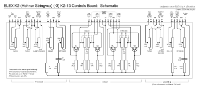

While I was at it I did the front board schematics too.

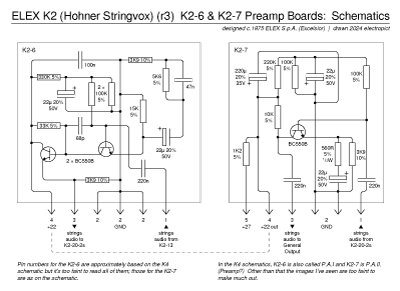
In drawing this, I found that the +27V to the K2-7 gets dropped over a 1K2 resistor before it’s fed to the board, and this lower voltage is also fed back out through the M175 to the K2-6. And it turns out that the same approach is used in the K2-9, which sends a dropped voltage back to the K2-14 board to run the pianos output amplifier. I also noted that the volume pedal attenuates the combined outputs of the K2-20-2 boards, by grounding them through the photoresistor in the pedal. Anything else that grounded the signal through any variable resistor would do the same job.
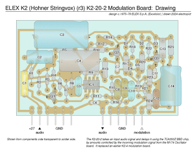
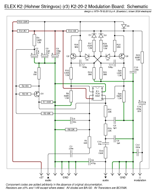
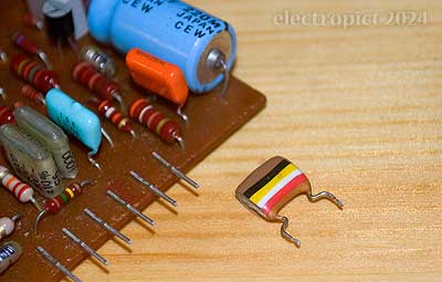
All three K2-20-2s have 100n tropical fish capacitors at C12, and while drawing these I noticed that one of them was cracked at one end, as they so often are. In fact all three are showing slight cracks but the one I was working from was bad enough that the end husk fell off with a little finger pressure. And I had one 100n orange drop left over that will fit in nicely, so I’ve replaced it. [1]
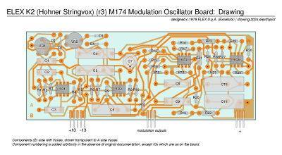
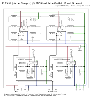
The M174 board was oddly difficult to draw and not just because it’s double-sided and has some of the B-side traces obscured by components.
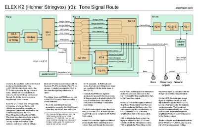
And here’s a diagram and summary of the tone signal route. It struck me while drawing this that the bass pedal connector only has wires for twelve pitches, C♯ to C, but the pedal board, as seen in 1970s adverts, has thirteen pedals. I can think of two possibilities — one (which would be regrettable), that the bottom C replicates the top C; the other is that the pedalboard has a divider in it to produce C1, or it divides the whole octave to produce C0–C1 (which would explain why it has a power supply). There may also be some envelope circuitry. [2]
And the contacts board. It contained a little surprise. In Ensemble mode, where I’d had the impression that four contiguous octaves played, as 1+2+3+4, it’s actually 1+3+4 for each of Strings and Cello. Drawing confirmed that what’s happening is, Ensemble mode switches power from the treble strings busbar to the ensemble busbar, and voltage is sent to an extra two wiring connection points within the board from the ensemble contacts, triggering a total of three K2-1 boards’ strings sides. The yellow wires fulfil the same function as the traces for keys F2–E2, but using wires keeps the board smaller. [3]

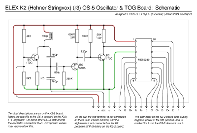
All that’s left is the oscillator and TOG. I notice that the component values are different on this one than on the other OS-5s I’ve seen (which were clocked an octave lower), and there may also be differences between these and the K4 schematic, but it’s too faint to be certain of those values.
For anyone who wants to study these drawings, especially as a working reference, a single file is probably more convenient. Download the full set as PDF (1·5MB).
Final Voice Repairs
Bass
[IN22:] With all that worked out, I’m reasonably confident in restoring the bass voice by putting a capacitor back in as C17 on K2-10. Sebastian’s K2-10 looks to have a capacitor identical to C16 there, where I have a big green 470n PET; so I might as well try a modern green 470n, not so big but still chunky.
Since this appears to have been deliberately removed, we should expect there to be a problem. Which might just be that someone disliked the bass voice and needed a capacitor; or possibly the original was too big and got squashed by the top panel (which seems to be the case with C1). Squashing isn’t an issue with the replacement as it’s about the height of the existing C10.
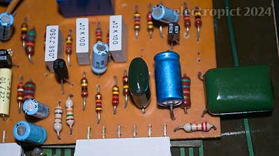
With the capacitor in, we have a bass voice, and I’m not finding any significant problems. When in Bass Mode there’s a little more background noise, but not much, and it’s still inaudible when it’s actually being played. The lowest two or three notes sound a little odd, a bit toneless, but that might be remedied if I turned the amp up a bit. Overall the bass voice is noticeably quieter than the others, but to really bring it out I expect you’d want to use the Bass Output.
I did wonder whether it might benefit from more capacitance at C17, but checking through the bass audio path there’s no other capacitor in it any larger than that; and indeed, the smaller ones are 220n, so we’re unlikely to get any bassier results by increasing it. [IN22 closed.]
Piano (with a detour back into Cello)
[IN21:] So C♯2’s sustain is too short and F♯3 is too loud. These problems move with the cards when swapped. Both their C1s tested reasonable in and out of circuit but while their DFs were within what I’d expect their tolerance to be, they were noticeably higher than most of the other capacitors I’ve tested here. With them replaced, both notes were normal immediately.
As for the Bs, you’d expect a failure at consecutive octaves to be a divider fault, but this can’t be as swapping the divider chips around has no effect. I swapped the B3 card; it moves the problem. I checked its C1. In-circuit, it gave quite a poor reading; once out it seemed quite good. But then with a leakage test it seemed pretty poor, staying well over 600µA after ten minutes, once we’d built up to its rated voltage. Which may not be causing the problem, but I’ve replaced it anyway. Testing that . . . no difference. On to C2 then. Similar condition. With that replaced, B3 is good.
While I was working on B3, somehow B1 & 2 pianos started working; not clear why. However, when I went back later, they were nearly or completely inaudible again. After a few minutes powered on they came back with no other intervention. A capacitor issue? Well, moving these cards doesn’t move the problem. So, what then? Bad contact in the sockets?
In fact, checking the thing again there’s a more general problem — the wrong octave seems to be arriving at B2/1 on the strings side too (whether the cards, including B3, are in or out), and the Cello voice is an octave high on B1 and B2. That may also be an intermittent problem, since I didn’t notice it first time. Swapping the dividers still makes no difference. I can’t expect to get the pianos right until that’s sorted. (Or it may be the same fix.)
Looked at with the ’scope, there seems to be a problem specifically affecting the B2 pitch output (divider 2 pin 12, routed to B1 terminal 16 & B2 terminal 15). The waveform, which should be a 123·47Hz square wave, intermittently turns into a 246·9Hz pulse wave about 99% high and occasionally goes all-high. Which would imply that the octave up is getting through somehow — or that its divider is being triggered twice, producing a positive square wave on both its rising and falling edges. Or perhaps it’s echoing, kind of like a network signal with no termination. But it doesn’t show up at the B3 output (divider 7 pin 5). There’s nothing obvious that could cause shorting, so to start with I’m putting some polythene under the board again. No difference.
The waveform going high or having a tiny pulse would cause silence as at key B2 or the very faint tone at key B1; since the differences are consistent I think I can assume that the problem’s affecting B2 more than B1, i.e. with slightly higher resistance near the B2 socket. Measuring resistances from div.2 pin 12 shows about 0·4Ω to B1 t16, and about 1·5Ω to B2 t15, so that could be right? I tried rubbing an 0·5mm drill bit up and down in the B1 sockets a few times with contact cleaner. (I’m not sure if you can get pipe cleaners about this size, but wouldn’t it be useful?) That didn’t get me very far, but repeating the process with B2 t15 seemed to sort it out. More or less equal resistances. And, powered up, all keys are now working on all voices, with no significant volume or decay length variations. Leaving it on for a while and playing it made no difference. I’ll try again in the morning because I’m not convinced.
Morning . . . in the bowl of night has flung the stone that puts repairs to flight . . . nope, no good. And scraping out B2 t15 socket again does not repeat the effect, and since the fault seems to be intermittent, may not really have done anything in the first place.
One possibility that’s been hanging around unaddressed because, not again . . . , is that the original solder joints may not be very good; ELEX didn’t always get great results from their wave soldering, I’ve found. A cracked solder joint is also perhaps a better explanation than this being an outcome of getting the right voltages from the PSU; I’ve been moving this board around a bit in the interim, and pulling the cards out a lot. That could have cracked something.
So I re-examined the photos I took of K2-2(a) a few weeks ago. I can’t say at this resolution, certainly not about the joints in question, but there do seem to be some possible problems, specifically on the junctions where the divider outputs come through the board. These boards don’t seem to be tinned through-hole (the technique may not even have been developed when it was designed in 1975, for all I know) and there are pins soldered through for most of these connections, but they have what look like dips in the solder around the pin. Or it might just be light not reflecting at those angles. In other words, yes, I need that biscuit tin again because I’m going to have to stand the board up and have a closer look at the underside, and probably reflow some joints anyway just to see if it’ll work.
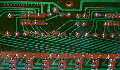
I took some close up shots of the suspect connections for B1, B2 & B3.
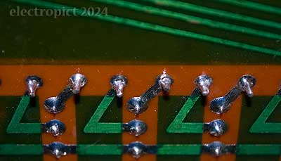
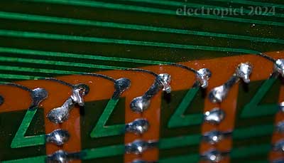
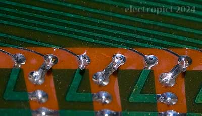
B2 only has one, but most of the through-hole pins in this row show signs of problems; mostly incomplete soldering, and mostly a little in what would have been the trailing direction for the wave machine, but to the front of the board where the trace on the opposite side pulled the solder away as the board moved over it. Then, under flash light at this angle, a crack in the board shows up across the pin hole for the upper-octave input at socket 31, though that shouldn’t be causing the current problem. I’ll reflow them for future-proofing. However, all the actual socket joints seem good; lower thermal mass presumably. [4]
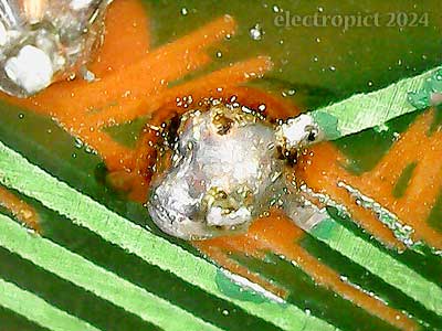
That said, I have previously established that the problem I’m having seems to be affecting the path from divider 2 to socket 19 t15, which doesn’t have a through-hole pin by the socket. Looking at the earlier picture again, I notice that further up the trace there’s an area where the original results seem to have been poor enough that there was some hand reworking by the factory, including some scraped lacquer around the through-hole pins, implying that the solder ended up a mess, and what looks like hand resoldering on the pin where the signal for B1/B2 divides through the board.
I wasn’t quite sure what I was dealing with there so I tried taking a microscope shot. Not great photography but it shows that it is just a big lump of solder; a good connection here shouldn’t need the lumps, but it happens. (Perhaps the soldering was done from above; solder drains through joints like this.) My hypothesis is that this is intermittently not making good contact with the trace running to the bottom right; that this is where the extra resistance is happening. I’ll reflow that too, and some of the others in the area.
With all that done, I’m getting equal resistance both ways. Looking again closely, some of the top-side junctions looked a bit empty too so I touched them up. Although I can’t be certain which junction really had the effect, testing B1, B2, B3 with a board in each, it seems to be working. So I’m fully reassembling.
After all this division, decay, and negativity, [5] I’m ready for some music. Will it make happy sounds?
Yes indeed. A big and sometimes happy, sometimes soulful, sound. And it continues to work, even with 20 minutes or so of playing, which should bring things up to normal operating temperature. I’ll still want to see how it works tomorrow so it’s been through another cooling/heating cycle.
Now we have the voices I tested the pianos and Bass outputs. Bass sounds less noisy on its output, but otherwise not much different. I also tried it out with a sustain pedal, and it works as expected. The pianos are a bit more noisy on the individual output, that is, there’s a bit of all-pitches feedthrough again. Not something you’d probably notice when playing or with a noise gate.
In the morning I played it till I couldn’t stand up any more, and it kept working. So that seems to be everything. [IN21 closed.] I’m concluding that it has the sort of sound that occasionally makes you hanker for the bass pedals just to add a note or two of emphasis. Or an extra arm. Also, that the C5–D5 strings notes, now with a good voltage, are maybe a little loud. That is, louder than the rest, or perhaps harmonically more resonant. E♭5–F6 are not quite as intense. The effect is glorious going on painful for some of the high notes in some tunes, and I wouldn’t change it.
One thing I do notice is that at times the sound is perhaps a little too much like an organ with a Leslie running fast — a classic sound, but not a strings sound. And at times I would like it to be able to produce that plain but very nice organ flutes sound that it was giving when the chorus wasn’t working. This implies that possible mods would be a switch to cut the M174 power (which is just the extra wires between the K2-20-left and M175 connectors, so easy), which would give you the latter, or preferably a small mixer board to blend between plain and chorus. But if you also have an organ you may not need it.
After a couple of hours of playing I noticed a smell of warm electrics, so opened it again and checked temperatures. The PSU is warm of course, but the warmest components outside it are the R5 power resistors on the K2-20-2 boards, all of which are around 28° (in 16° ambient). Which is well within range for instruments like this, and cooler than some.
Tidying Up
Voltage & Power Confirmation
Since everything now seems to be working, I’ve checked the PSU outputs one final time. Under load (except terminal 5 which only supplies the volume pedal), the terminals are:
| Pin | 1 | 2 | 3 | 5 | 8 | 9 |
|---|---|---|---|---|---|---|
| +26·7 | +20·5 | +12·9 | +26·7 | −14·0 | −22·2 | |
| K4 | +27 | +20 | +13 | +12 | −15 | −26 |
| (K4 schematic figures given for comparison) | ||||||
At this point I can see no reason not to take the K4 figures as the original design intent, so I’ve written them into all the drawings.
I’ve also checked its power consumption. Unexpectedly, it’s nowhere near the rated 10W. After a switch-on inrush where my meter went up to about 30W it settled at about 22·5W ± ≤0·3W. This fits in quite well with the 25W rating that some of the K2r2s had on them, so I don’t know what happened there. I don’t think anything I’ve done here could have increased its power usage by 150%. Maybe they ran out of 25W numberplates during this batch (and other batches), and just stuck a 10W one on anyway. 10W did seem low. I’m going to leave the T500mA appliance fuse in as it should be able to handle a great deal more than that, and it’s already survived some of the greatest strains it should ever need to face during repair. The numberplate could do with its voltage rating relabelled anyway as the old label is wearing off, so I’ll make it 25W while I’m at it.
Insulating Covers
[IN14:] For the PSU top cover I don’t want to replicate the original as it was rather large anyway and I’ve replaced much of its function with the new fuseholders. It’s been some decades and many setups ago since I folded perspex, and never 2mm perspex, which presumably heats and cools that bit faster than the heavier grades. As it turns out, it doesn’t respond very fast to low heat (heat gun at c.200–250°) and is prone to cracking; but at c.350°, while it does soften enough at a reasonable rate, it seems also to warp a lot, bending towards the heat, presumably due to the polymers bunching up as they toast. After a couple of failed attempts I got the folds roughly where I wanted them and no cracks. This would all be a lot easier with a jig, but I only have a couple of vices and odd bits of metal bar to shape it with. I had to drill out some cutouts for existing nuts and screwheads. (That introduced some cracks.) I was able to use the original screws I’d found to fasten it to the PSU top. I’d chosen to make the cover 90mm long and position it roughly centrally over the terminals and M282 board, only to find that it didn’t fit under the keydeck panel when it came down. I shortened it by a few millimetres and tried to bend the excess down at the top but it ended up quite distorted in the heat. I should have done that last bit at lower temperature I think, or maybe made some sort of clamp to keep it straight. It’s functional though, and I don’t want to waste the perspex.
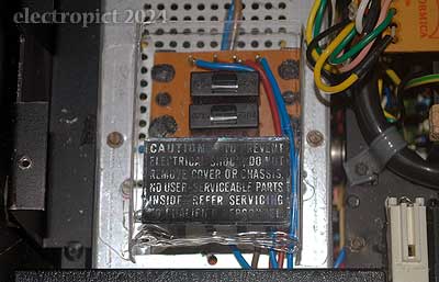
I did consider making a replacement rear cover, but it’s a more complex shape, and the fold lines are shorter, which based on the last experience wouldn’t make anything easy. More importantly, considering it in detail, the biggest problem here is the mess of wires that run through or beside it. I was a bit doubtful about being able to get something as solid as perspex in without cracking.
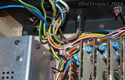
I tried putting the old one back in experimentally. This turned out to be harder than I’d anticipated, and required unscrewing the keydeck again and propping it up. Working on the basis that it should divide the mains AC from the internal DC wires, I had to pull the screw-in tab forward with some needle-nosed pliers to get it in position. I’m now very doubtful about the option of making a replacement. Once it’s in it seems to do its job, and there isn’t anything really corrodable under it. In fact, it’s open at the left end so shouldn’t be producing a moist microenvironment anyway.
But looking at the result, with the DC harness outside, although the cover fits better at the base, it bends under the pressure from the wires, and they are under rather sharp pressure from the keydeck chassis when down.
Checking the earlier photographs, the DC wiring harness was inside the cover when I got it; I’m not sure that’s original as, while there’s a cutout at the top where the harness could pass through, there would also need to be one at the bottom. I’m really not sure what the best solution is, but I’ve put it back inside, wrapped the DC wires with harness tape where it’s close to the mains wires, and have cut an opening at the base for the I/O wiring, to let the cover fit better. The bass pedal connector wiring harness is left outside the cover. The chassis will still press into the cover but I don’t think it’ll be as distorted as it was. [IN14 closed.]
And a little wire insulation . . .
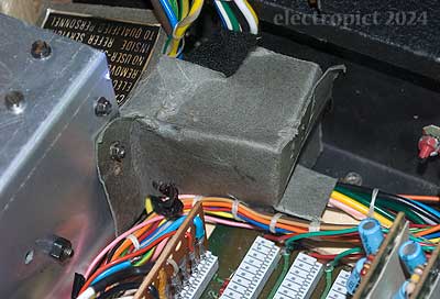
As shown in the photographs above, one of the wires onto the K2-left connector has an inch or two soldered on at the end for no obvious reason, with an exposed joint. The older photographs remind me that there was a piece of insulating tape on it originally, which must have fallen off early on. It wasn’t close to any other conductor in the interim and I didn’t want to desolder it just for heatshrink. But we’re at the point where it needs to be addressed, so I’ve replaced it with some of the new ‘liquid rubber coat’ I’ve been using recently. This is the first time I’ve used it to replace sheath, and I’m interested to see how it works out over time.
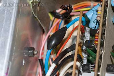
My impression while moulding it on was that in this case the soldered wire spikes on the joint were still too easily felt and wouldn’t be covered by more than few micrometres of the black stuff, so I did a second coat once the first had cured. If you have time, even if you need two coats this is easier than trying to wrap self-amalgamating tape round a wire in a very restricted space, so I think it’s preferable.
Keybed Bolts
[IN9:] Replacement ‘cheese head’ bolts are available, so I got two. (Don’t think I’ve heard the term ‘cheese-head’ before.)
But it couldn’t be that simple, could it? When I put the left (previously missing) bolt in, it met with nothing. Thinking I might need to tap a larger thread, I took a closer look at the hole in the chassis bar. Surprisingly large; nearly the width of the bar itself. The other one seems to have a sort of captive nut inside the bar. Never seen (noticed) that before. I don’t know how you’d go about it even. I mean, you can’t just glue it in or . . . this would happen, I suppose. Under any sufficient impact, the nut would break out. Right . . . Probably this was part of the same event that knocked the locating pin out and maybe also the left-end hinge support. (Occupational hazards of being an extremely heavy instrument. )
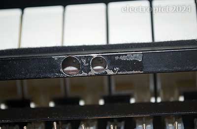
Actually once I see the photo of the right-hand hole, it’s not a captive nut but a thread insert. That would originally have been inserted under pressure; a bit easier to fix in if I had one, but not easy, and unlikely to be reliable.
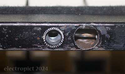
I looked for threaded thread inserts but couldn’t find anything suitable. So how else would you do it? I don’t have any M4 nuts that would fit into the bar. Even if I did, you couldn’t . . . I think . . . weld the nut in, inside the bar. Or it might be possible with some spot welding equipment, or maybe TIG, but I don’t have either. You could solder it in, maybe, by sticking it in with solder paste and heating the bar around it with a blowtorch? There are ‘metal glues’ available now but I haven’t tried them, and I don’t know how well it would work if you had to put glue on a nut and poke it in about a foot and precisely position it . . . Or you could just fill the hole by MIG and tap it, but even using brass, that’s still a lot of heat that might warp the chassis, and it would need the whole thing dismantled again.
The best thing I can think of is to make an insert that slots into the bar from the end, and bolt it in horizontally to keep it in place. That should be reasonably secure? Maybe there’s a metal-glue solution to keeping it in place, but I’m not sure it isn’t better to have it a little loose so the tension from the main bolt doesn’t crack it off. That’s a plan, then.
The chassis bar interior is 13·5 × 7·5mm (at the end anyway), so I decided to weld a couple of short offcuts of ¼″ square steel bar together. It would have been easier to get some flat bar about 12×7mm but I didn’t want to wait. Then it took a week for the screws to arrive anyway. And we had about three weeks of constant rain and/or stormy weather, and I lack a covered space for welding so . . . wait. Finally, a dryish day with almost no wind. The first attempt worked up to a point, though a milder steel would have been better — blunted some of my drill bits. But it wouldn’t quite fit into the chassis bar (which turns out to be not quite square at all corners) so I tried to file it down. This failed, as the remaining weld cracked under pressure from the file. I could have tried to file some bevels for rewelding, but I wasn’t sure it would still match the threads I’d cut, aaand here’s the next storm coming.
I don’t have enough left of the original bar for another try. I looked online. It’s that time of year when everything’s shut, but I found someone selling a short length of ¼ by ½ brass bar. I’d prefer mild steel but brass will be easier to drill and tap, and might still be stronger than the original threaded insert. I cut 50mm, rounded the corners off a bit, drilled and tapped a hole, and filed a groove out for the locating pin. I inserted it experimentally, and it stuck, first at the point where the upper bar of the chassis is welded on, then on each side of both holes in the chassis. (This required a rod to poke it in and a length of thick wire to poke it back from the other end.) I filed it down some more each time; it went in all the way when I got it down to 11·38mm tall. You could probably just start with a 10mm bar or (11mm if you can get it) and save some effort, but it’s reasonably snug like this so should be less prone to movement. I drilled holes in the chassis (a little loose at 4·5mm) and countersunk them, marked their position on the insert, then drilled and tapped those holes too (M4).
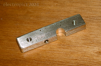
Using brass, the insert wasn’t too difficult. I’ve left the screws not quite tight, but with high-strength threadlock. Once it’s set (with one of the keybed bolts in tight to keep it under vertical pressure) it can still move a little, perhaps ±0·25mm. [6]
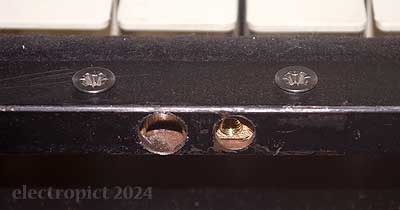
I replaced both keybed bolts and washers for the sake of uniformity. With that done I can hopefully put everything back together. [IN9 closed.]
Top Panel
There were a few final assembly details. In particular, I had one screw left over between those I removed and those I’d found, so I thought it was probably the one intended to go in the chassis left end through that rubber washer. Since this is the same flanged hex/slot screw as ELEX used almost everywhere, it — and the washer and screwholes for it — seem likely to be original. So I put it in
The last thing is put the top panel back on. I hadn’t done this in all this time because it looked likely to be difficult and perhaps even damaging. Turned out to be worse than I’d expected. One point to note is that — I checked the original photographs — the washers along the front edge of the K2-110 board are extra spacers under the board rather than between the screws and the board. Even so, it’s quite hard to put the panel on. This probably puts a significant amount of strain on the pushbutton switches. It also puts strain on the sharp keys, and scratches them. I did try putting some paper under the edge of the panel to prevent this, but it seems to need all the space it can get. I got it on eventually. [7]
That was only the start though, because now the mode switches don’t cancel under their own springs, and have to be pulled out by finger, which is not a realistic option for performance. They seemed to be under some downward pressure so I tried releasing the panel and propping it up a little but that had no effect. If anything it now looks as though the pressure is from the left. I also tried a little key lubricant with no effect. Pressure on the right end of the panel did improve things, but with the screws tightened that becomes impractical. It occurs to me that that rubber washer and screw in the left end of the chassis might be the cause of this. Maybe just remove the screw since I’m not sure it was original anyway? I took the panel off again, with some difficulty. It’s also possible that the whole point of the hole was to be able to adjust the panel to the left with a screw, or pack it out on the outside with washers, until the switches do work. Which seems likely to be unstable, and there’s little advantage to it while the panel is so difficult to attach and remove. If it’s that position-sensitive, they probably shouldn’t have bothered with the collars. You could just remove them, but I went for a middle option and took this opportunity to file and cut a little out of their lower edges, aiming to get the depth of the collar down to about half its original height at the lowest point.
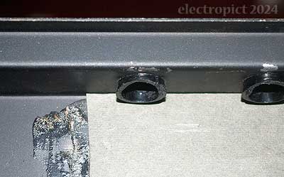
This made reattaching the panel much easier, with the buttons just clicking into place with hardly any encouragement. To avoid excess strain on the switches and the K2-110 board I’d recommend this modification for any K2 with this problem (which may not be all of them). This time I left the end screw out. With the panel loose, the pushbuttons operate properly, but tightening the screws again I seem to have the opposite problem; too far to the left. So I took it off again. (Also much easier than before.) I considered adding a washer on top of the one that’s already there, but there isn’t enough room. I tried some paper, but it didn’t make much difference. I wonder whether this is really the problem, or whether the position of K2-110 can be adjusted? I opened up again and loosened the whole K2-14 and K2-110, and retightened them pushed hard to the right. This made a bit of difference, and the switches now more or less work with just the rubber washer, though the Ensemble switch still seems a bit sticky occasionally. I’ve noticed that the sticking seems to start when the right-end screws are tightened, which pulls that end back a millimetre or two; perhaps it’s the relative angle of the panel and K2-110? Or perhaps that missing screw by the Split Keyb. switch should be replaced, which would pull at least that one back a little . . . but then, it would tend to force the switch to the left which is the opposite of what we want. That might even be why the screw was removed in the first place?
Well‚ I tried it anyway. I found a short M3 screw and a nut, and tried fitting them. They might not have been there originally, because the bracket doesn’t fit with the screw through it; it’s too tight to the switch block. So I filed the upper edge down by a bit less than a millimetre. With it in and everything together, the switches move a little easier than before, so maybe that’s it?
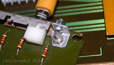
The Full Keyb. switch is now the worst sticker, only failing to cancel when the Split Keyb. switch is pressed and not always. But it still depends on the lateral position of the panel. I tightened the screw into the side hard this time and the panel can’t really move much further left. Good enough? Ehhh . . .
Cosmetic Surgery
There were a few holes and rips in the tolex which needed repair. Most of the repairs are visible, but the surface is stable and as watertight as it’s going to get. Just a bit scarred when you look close. And there was some rust on the hinges. The paint on the Hohner logo plate has scraped off a bit, but these paints on aluminium aren’t very stable, and I’m not sure that there’s any way of replicating the original. If I were to do it, I’d probably want to etch the plate with black pigment. But unlike the rips and rust, repainting wouldn’t prevent anything getting worse, so I’ll leave that, for now at least. Fortunately, the inside is in good shape; a few scrapes in the paint, but not heavily rusted like some. [IN3, IN4 closed]
[IN5] Then, what to do about the missing plastic edging around the I/O panel? There are various types of plastic profile available but nothing quite like this. Since it’s an option now I might see if I can get a replacement 3D-printed, which seems likely to give the best outcome as it could be made as a single piece rather than in parts like the original, which obviously isn’t especially stable. Alternatively something more flexible that would just mould round the edges . . . but getting that reasonably consistent may be hard. But its only function is to cover the wood and hold the tolex edge down; it doesn’t need to be too strong. To be considered for the future.
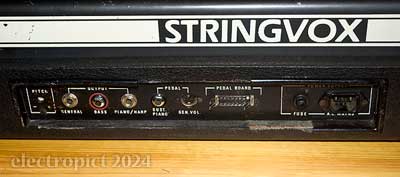
Finally that missing bass-range marker tab. [IN7] I’ve been turning this one over in the back of my head. I’m actually a bit reluctant to do it, in part because to get an exact match to the original plastic would be unpredictably difficult, but also because I just don’t like these marker tabs. They’re a bit cheap-looking, and somehow cheaper on the blacktops than the silver. It would be easier just to take the remaining one off. If you need to remember where the split is — and I think I probably do sometimes — it would probably be better to just have a paint mark for it, so I’ll think about that later. (I’m also mulling over getting the top panel resprayed and restencilled anyway, to deal with the paint damage. I have another couple of keyboards needing that too so I might as well learn how it’s done. But it’s looking likely that I’ll need to take a break from repairs this year, so — later.)
Upstanding
I got new hand-turn bolts for the stand. They’re black metal rather than plastic heads, and much of the black came off on my fingers within the first few minutes, but it settled down. The stand needed a clean up and the crossmember needed derusting and painting. It came out reasonable. This isn’t the type of crossmember (or quite the same rotation plate) seen in original marketing materials for the earlier K2s, where they were double bars, which I think would resist lateral movement more, and for some purposes you may need that, given this weight. But I haven’t seen any pictures of another r3 on its stand, so I’m not sure of that. This isn’t the original stand anyway, as the crossmember isn’t long enough to allow the ends to attach plate-inwards, which means it can’t be rotated much. I might make a new one at some point, but it’ll do for now. [IN2 closed.]
One thing I’ve been wondering is how you’re supposed to get K2 on stand. This, again, is about 34·3Kg of keyboard, and it has to be screwed in at each end separately. I’ve never done this manoeuvre with any of these end-attached keyboards. I assume the stand should be connected while the keyboard is at rest on the floor, then pull up.
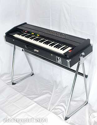
That works. But there’s quite a bit of lateral wobble. And the crossmember really should be a little longer even with the stand ends the wrong way round, as they still angle in by a degree or two. The keyboard height isn’t quite right for me standing, though sitting isn’t bad. The stand does allow about ±10° angle adjustment, which makes it just about playable standing. In fact the keyboard isn’t well balanced on this axis, and tends to pull down at the back. The rotation plate has no lock, and there’s a limit to how tight you can get the knobs by hand. This may be because the original ribbed rubber has hardened a bit. I’ll see if I can replace it, or insert plain rubber discs for extra purchase. [IN23: replace or improve stand rotation friction pads.] And hopefully this year get time to make a proper crossmember, when the weather’s up to it, and maybe add some bracing against lateral movement. [IN24: make new stand crossmember]
There’s also going to be a reverse process at some point, of letting the keyboard back down to the floor to get the stand off. If I don’t add anything about it later, assume it didn’t cause any lasting damage.
(Update, 2024-01-30: It turned out to be safer and easier to tip the keyboard back to rest on a box about half-way down. It would be better on the way up too. In this case the box was an amp, which would be convenient in concert conditions, but anything solid enough would do. Having the right length of crossmember would make things easier too.)
Repair — Coda
I mentioned possible instability in the lateral position of the panel? Once the K2 was on its stand I found that in the course of the required manoeuvring the switches became stickier. So I took the lid off again and gave it a rather despondent examination. But from the new angle, I noticed that the front edge of the modes switch block was a little curved forward when compared to the line of the others. And realised that the other option I hadn’t considered was that the original intent was to have the bracket in front of the switchblock, keeping everything in line. [8] So I took it apart again. I found that with the extra thickness of the switchblock behind the bracket, the nut for the underside bolt can’t fit in together with the screwhead I’m using for the front. Perhaps there was an original smaller screwhead (or perhaps that’s why it’s not there), but that’s the only type I have to hand, so I filed a bevel off the nut. And that’s it in, almost exactly in-line with the others.
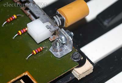
Reassembling the panel then . . . is it any better? Well, no. Getting the panel on was a bit harder than before, with the Full Keyb. switch sticking hard. That may be a one-off thing. But in use the Ensemble button now sticks most of the time, and levering the panel to the left still frees it up.
Another Little Diversion
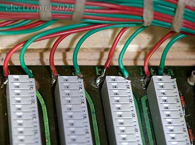
While the panel was on, I had powered it up, and found that there was no sound from E5 piano/bass. So with it open I went fault-hunting. It didn’t move with the K2-1 board, and the signal at the K2-3 board terminal (60b) is good, so I expect we’re looking at another solder joint problem on K2-2, perhaps the result of a bump while I was getting it on the stand? That means getting the K2-2 out again? Well, once I got a torch into it the problem was obvious — the wire from K2-3 had broken off its solder joint behind the K2-1 socket. This must have happened while I had the keydeck up on edge, dealing with the bolt insert. It was a quick fix after all — with the top four K2-1s out of the way it was only necessary to pull K2-2 forward a half-inch or so to get the soldering iron into it.
Back on Track?
So I tried replacing the panel again, with the screw into the left end tightened harder. I’d been considering whether it might be possible to bend the top panel support brackets a little, and since the top was off I had a look. I tried bending them both to the left experimentally. I don’t think I had much impact on the left end, but may have got the right end in a couple of millimetres. Does it work? Yes. All the buttons now operate and cancel freely. I believe I now have a fully functioning instrument. I mean, for the time being.
Conclusions

Although this was ELEX’s top-end product in the K series, and it has a few quality improvements to the standard of the early K1s, the K2 is still not especially well made. It’s unsurprising that the brand was subsequently shut down (which is why some of the K2r3s are Excelsior branded), and eventually Excelsior abandoned the keyboards market. Albeit at a higher price, the quality of imports from Japan was unmatchable; requiring significant changes to production methods that few European manufacturers were prepared to invest in — and in this market, none successfully. The sound quality is usable, but nothing like as flexible as Korg, Roland, and Yamaha products of the day. Rehashing the earlier product in 1979 wasn’t going to achieve much, even with the third delay increasing the richness of the strings voices. These were keyboards at budget prices, but when you take into account its weight . . . it wasn’t going to be popular.
As a repair task, I’d rate it challenging. It really isn’t well designed for maintenance, largely because of the difficulty of manoeuvring the top panel and PCBs. That could be worse, of course; there are many connectors rather than soldered joints, but in the r3 even they frequently use alternating pins and blanks, and several of them can be reinserted in the wrong position. Also the large variety of screws and unclear wiring, and the inaccessibility of the voltage trimmer in the PSU. Most of all, the choice to use a hinge type on the keydeck chassis which prevents it opening with the top panel attached, or opening to or past 90° without it, where a simple cord could hold it steady while you attended to contact springs. (And you could take better photographs!) And the difficulty of getting the top panel off and on (though that at least is fixable). Anyone attempting one of these should at the minimum come prepared with one or more decent props for the keydeck, a 4mmAF bit driver, a multi-compartment sorting tray (more compartments the better, starting with about 20), and pen and notepad to take precise notes of where all those different screw lengths came from.
Reselling one of these commercially after doing any substantial work — including just a proper clean — is an unlikely prospect. Doing it for yourself, though, do you get a worthwhile instrument out of it? I’d say yes, if you’re into that sort of thing. It has a slightly greater range of options than the ELKARhapsody 610 to which it’s often compared, and perhaps as good a sound; but not quite as good a Strings sound or the flexibility of the String Melodys, and the r3 doesn’t have the sound or range of the contemporary String Performer. And I get the impression that it’s a harder refurbishment than any of them.

| outstanding | IN5 | replace plastic edging round ports hole (or make consistent somehow) |
|---|---|---|
| IN7 | reimagine missing marker tab and maybe paint & restencil the top panel | |
| IN23 | replace or improve stand rotation friction pads | |
| IN24 | make new stand crossmember |
Appendices
For additional information about this repair job and the K2 / Stringvox generally, see Hohner Stringvox repair appendices.
This post has been updated in Hohner Stringvox repair appendices.
Comment or Question about this page? write
Notes
- Under the paint it wasn’t too bad; some of them fall apart when the paint cracks off, but here the leg seems stable. So it might still be usable if I put some epoxy over it, but I’m probably not quite obsessive enough about them for that. In any case, this board appears to have had all its components’ leg ends squashed flat and wide to keep them in the board for soldering, so I had to reverse that with pliers to get the cap out; hence it’s not really suitable for re-use. This is slightly easier to deal with than having the ends bent over as on most of the other K2 boards, but still a really bad idea in terms of maintenance. ↖
- Compare the ELKARhapsody 610, where the optional bass pedal used one divider chip to produce C–E below the inputs from the keyboard’s F–C, and which has its own (pre)amplifier with its own volume and sustain controls. ↖
- It occurred to me while drawing this that comics artists have been arguing about (mostly disagreeing with) the practical use of the ‘infinite canvas’ for decades now, but I wonder whether the negatives really apply to circuit diagrams? ↖
- I believe more recent wave soldering has the option to control solder flow rates in particular areas of the board both laterally and over time, to avoid these sorts of problems, but earlier it was a question of balancing the speed of movement for the whole board between complete coverage and too much heat. Not always successful. Designers at the time were perhaps a bit enthusiastic about the size of boards that could be made with these methods. ↖
- Might make that a track title. ↖
- I would have preferred not to drill into the chassis. If you really wanted to avoid it another approach would be to put the insert on a rod and keep it in place with a compression block of some kind at the end. I couldn’t see how to make that with materials to hand though. ↖
- This kind of design flaw is probably part of the reason why Korg, Roland, & Yamaha kind of took over the market. It can’t have been easy to assemble these at the factory, even. As far as I can tell, the K3 had its buttons angled up slightly to make the whole thing easier, but they didn’t reimplement something like that for K2r3. The K3s I’ve seen didn’t have collars either, and the front panel angle seems also to have been sloped rather than vertical. Which may be overkill — and I approve of that. ↖
- I did check Sebastian’s photos to see how it was done there, but the bracket isn’t there at all. It’s not clear how the Split Keyb. switch is held steady in that revision. ↖
Article text ©2024 Electropict  .
.
Click images for individual licences.
