Seizure
Some graphics for democratic computing. The text is a line by Cory Doctorow. This page is a public draft, and may be altered or the contents moved to some other server in future.


This is a list of articles with teasers. The headlines below are links to the full articles.
Some graphics for democratic computing. The text is a line by Cory Doctorow. This page is a public draft, and may be altered or the contents moved to some other server in future.


Question from ALF, 2025-09-29 13:23:46
Hey! I'm ALF, from Italy. I found your great website looking for technical info about the KORG SD-400 Signal Delay. It works but the repetisiona are quite noisy (with some "air" blended with the original sound). I think it needs some fine tuning of the clock/bias. I opened it, founding 9 trimmers! I found the ones are responsible for the feedback amount. Could you provide me any schematics or give me any advice about this process? Many thanks in advance. Ciao for now! ALF
Response:
Unfortunately I don’t have any technical information about either the SD‑200 or SD‑400 apart from the user manuals (which aren’t very detailed). It took me about ten years after first getting one to find those! And since mine have been working I haven't tried adjusting any of the trimmers. I’ve been thinking of working out the circuit some day though.
I had this thought about gender-fluidity, which on consideration may illuminate the subject of gender more broadly.
Having met people who assert a variety of non-binary gender identities over the years, I’ve always been a little puzzled by the concept of fluidity, compared to gender as a reasonably constant thing. (In the absence of some major event requiring transition, though that’s more often a long-term mismatch rather than a specific event obvious to others.) I had no reason to disbelieve anyone, but I somehow didn’t get it.
I have considered that perhaps a very neutral position on the hypothetical feminine-to-masculine spectrum could produce a variable gender identity, if external influences could then overcome the neutral state. But that doesn’t clearly explain why there are people with fluid and people with consistently neutral identities. I also tend to think that masculinity-to-femininity as commonly practiced is not a single-dimensional spectrum, but rather a very approximate two-dimensional aggregate of characteristics which derive much of their imagined grouping from social influences anyway. However:
It occurred to me recently that another way of looking at it is that fluidity might be the norm. That is to say, that ordinary humans don’t necessarily have a real permanent sense of gender identity to begin with, rather than intermittent ones which are assumed and reified in between times. As someone once put it, ‘I don’t wake up every morning and immediately think oh-my-god-I’m-a-woman.’
Some more notes about the Behringer 2600.
A point which isn’t quite clear either here or in some of the pictures of the ARPs is what the function of the S&H external clock input is. But the later (orange) ARPs clarify that in the panel layout — the jack is an input to the S&H circuit, replacing the internal clock. Consequently it can be used to time the circuit separately while the internal clock is still triggering the transient generators.
Wondering what the actual transient times were, I connected up to an oscilloscope and found that the ADSR attack is surprisingly short in proportion to the other times. This remained the case at all time settings.
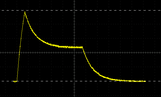
I measured the following maxima:
Since it’s a matter of occasional confusion, even amongst people doing synth repairs for a living, I thought I might try a simple description of how divide-down polyphony in analogue instruments works.
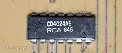
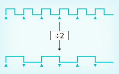
The basis of the technology is a circuit called a frequency divider. [1] This can be done differently with digital manipulation, but a typical analogue frequency divider responds to a (significant enough) change in input voltage by waiting until a similar change recurs one or more times before changing its output. The simplest and commonest division is the one-half or first suboctave, where the count is every two cycles. (A binary divider. n.b. divider circuits are often also known as counters.)
In electronic instruments, input to dividers typically comes from an oscillator circuit. Originally, each of the notes in the top octave of divide-down instruments were generated by a separate individually tuned oscillator. The collection of oscillators this required is usually referred to as an oscillator bank.
(This is the last article listed on this page. Skip to page navigation.)
I
I want this case to be as compact as possible, though I don’t really know quite how this is going to fit together. I’m thinking it should be possible to fold the aluminium sheet so that it clips into the middle screw groove in the top and bottom extrusions of the (captive-nut) racks, thus avoiding any exposed metal edges. If it works, it should also be possible to fold a front and back plate over a base and then hold them in with a small number of screws.
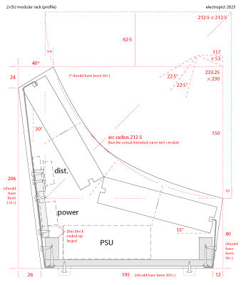
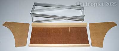
I cut the ends out of plywood with mostly a handsaw, but using an electric jigsaw for the curve (which I drew freehand on the wood since it wasn’t trying to be circular anyway). The curve didn’t quite work out thanks to problems with the saw and clamps, but some work with a flap sander improved things. [2] The racks have countersunk ⌀3·5mm holes at either end, presumably on the basis that minimising protrusion is good. I had to buy some bolts, but couldn’t get 3·5mm so I’ve drilled the holes out to 4mm. Washers and Nylock nuts on the outside.
At this point things are a bit rough; the plywood could use a little filler but the aluminium can just be sanded and primed. Both will be painted. Black, because, black.
I’m also intending to line the wooden parts with aluminium foil. I wasn’t entirely sure but eventually decided to go with a thinner plywood scrap for the base. The front and rear support strips are another offcut of something, cut longitudinally. In practice the plywood I had for the base turned out to be a bit curved so I used a larger offcut for the rear support strip to help straighten it. The ends screw into these, making the assembly quite solid already.
