(Or closer-to.)
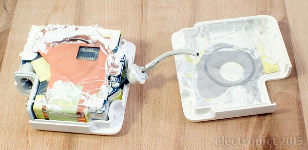
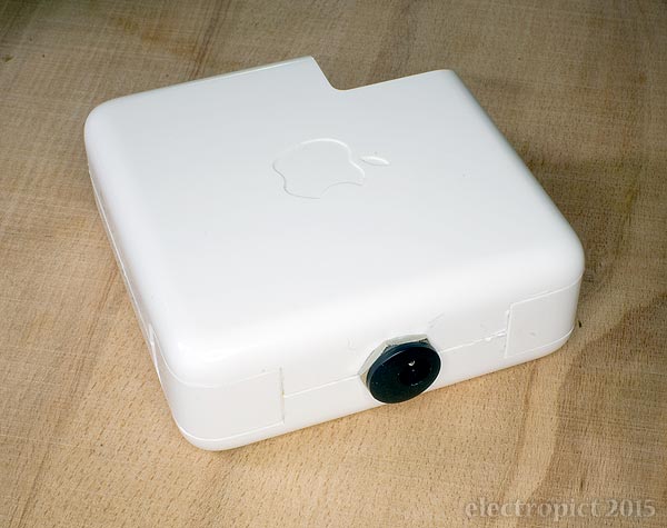
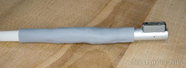
Since I last wrote on this topic I’ve been living uncomfortably with my fourth Apple MagSafe PSU in a temporary-repair state; and many other things have been getting in the way, some of which have been much more interesting than fixing old PSUs. But recently the (now, what, 18-month-old?) cable on Nº4 has shown additional signs of deterioration, requiring further bandaging. Won’t last long. So on to a full refurbishment of Nº2, which (including previous emergency repair) looks like this:
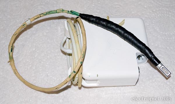
As the migrant plasticiser had almost completely evaporated when I took photos last year, there is no significant further deterioration, though a few flakes of sheath have fallen off. The plan was:
“3. Whether or not (2) is successful, open up Nº2 and replace the whole cable. I did look for something similar in the way of coaxial cable last year, unsuccessfully. But I suspect this isn’t necessary; it’s just a DC power supply. Ordinary 2-core flex should do — though all things considered I think I’ll opt for heat-resistant. Ideally this should include putting a socket in the adaptor, so the cable can be replaced if need be. This will probably not look very elegant . . . but nor does it in its existing state.”
So, to work. Start with cutting.
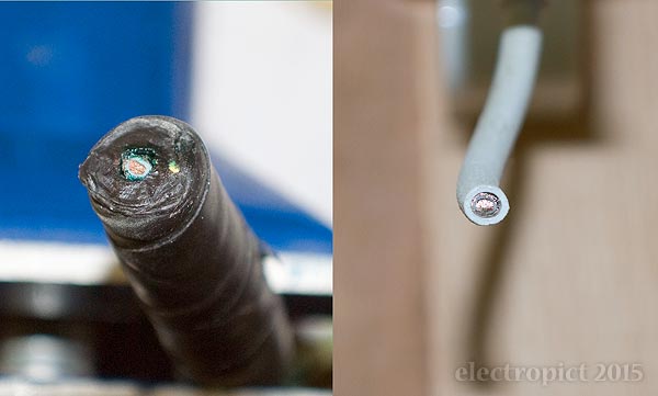
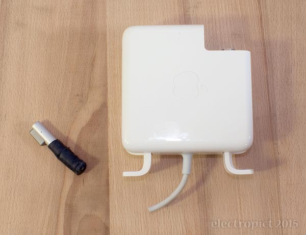
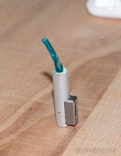
I think I mentioned previously that the original application of self-amalgamating tape was . . . excessive? Enthusiastic, anyway. It worked. We shall try to achieve something marginally more elegant this time, right? The core of the cable is grey-insulated. (I do not know whether this is universally the case with these PSUs.) The deplasticisation effect has not travelled all the way up the cable — the last six inches or so is as-new, and has no green goo inside. Old cable dumped, we’re left with the MagSafe tip, and the adaptor. [1]
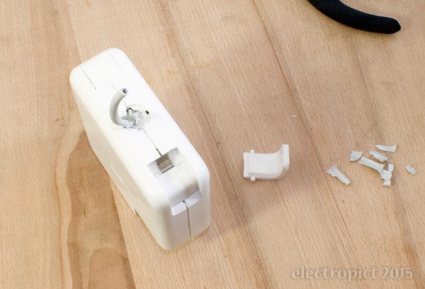
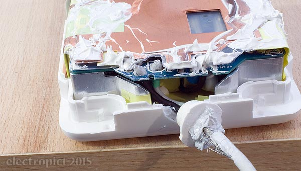
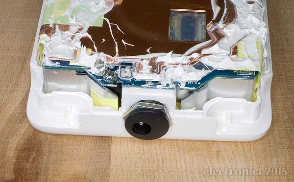
First, the Adaptor. Getting this open is likely to be the trickiest part of the process. (Or maybe that’s optimistic; who knows what is to come?) I know it doesn’t unscrew. I’m not clear whether the parts just clip together or are glued/sealed somehow . . . I find that it is possible to put enough pressure on the sides around the cable hooks to open the case a little and remove them. In the course of this I also conclude that the cable strain relief on this version of the PSU is firmly bonded to the cable, and can’t be easily pulled out of the case, so I’ve cut into it to see how it attaches. This exposes some retaining tabs in the case:
Some further application of pressure around the case allows it to open fairly cleanly — actually quite a bit of pressure, carefully, over a period of about ten minutes. I’m still not sure whether it was glued or what. It may not have been necessary to cut the strain-relief. Inside the case there is what I assume is thermal transfer paste, which may also act as non-setting glue. Messy.
The strain-relief block seems to be co-moulded with the cable in it. This is a major improvement on the original PSU with this MacBook. Ain’t no way in California this sheath is going to pull out and expose the conductor. (A belated round of appreciation for that conceptual improvement . . . though, obviously, the implementation is so poor I’m now cutting it out to avoid the annual replacement expense . . .  ) Inside the block, both wires are sheathed (ground in black), and there’s not much of them. I cut them as close to the block as possible.
There’s not much space inside. The remaining wire could, in principle, be connected direct to the new flex, but providing adequate strain relief and sheath clamping would be difficult. A socket sidesteps the question neatly. I’d prefer a socket anyway, especially as the new cable is too thick to wrap round the built-in hooks for storage. Apple should have used sockets from the start, as I’ve said in various places over the last few years. Homo sapiens pernickitens I may be, but I’d not be too worried by replacing a fraying cable every year or two, so long as I didn’t have to pay £130-odd for the PSU every time. Even if it was an own-brand connector, of a radical new design that resists accidental disconnection, and keeps third-party manufacturers at bay for a few weeks. If it was just affordable and tolerably well-constructed.
(While I’ve been doing this, I read that Apple are now moving to charging by USB; MagSafe is over anyway. Interesting, but too late. And no word about cable quality, which is the main issue.)
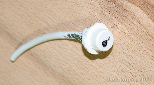
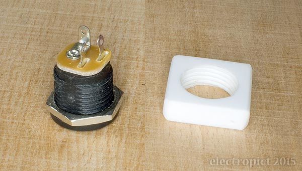
What I’m about to do will not be all that well-constructed — because getting exactly appropriate bits is difficult when you can’t order them bespoke, in six- or eight-figure quantities. But it might be better than Apple’s approach. At the Adaptor end, since a 3·5mm jack would be a bit long, I’m going to try a simple coaxial connector. Getting the right one is difficult; it has to be small enough to fit into the case (though packing out with washers is an option) and simultaneously capable of handling the current and voltage. (4·5A @ 18·5V max. for these 85W PSUs.) I haven’t been able to find an ideal one (with full specs), so I’ve gone with the best available based on conductor areas. (As it turns out, the terminals inside look smaller than I’d like.) The supply pin is just — only just — recessed enough to avoid contact with external conductors, but the supply’s ELV. I’m not completely happy with this, but we’ll see.
The socket has a 12×1mm thread. (Not M12-extra-fine; even finer — 1mm pitch.) That requires the original strain-relief block retaining tabs to be trimmed out of the case. It came with a small metal nut, but that can’t go inside, so I spend an hour or so making a plastic nut. (Had to buy the tap.) This is 4mm thick, because that’s the plastic sheet I’ve got in — 3mm might be better. I’ve made it roughly rectangular, 17mm wide to fit between the interior projections in the case, and 18mm high, rounded top and bottom. Much higher and it wouldn’t fit under the PCB. Probably 17mm square would be best if buying something; or 16mm, to be sure it doesn’t put undue pressure on anywhere — but I don’t want to get too close to the thread, so I’m leaving it at 18. (Smaller-diameter sockets are also available, but then you’d have a less secure mounting over the existing hole. That would be resolvable with a washer outside.)
Prise the lower side of the case back a bit, solder the wires on, with heatshrink, and clip the nut in, screwed to the appropriate depth. All this would have been easier with more cable inside, so next time (Nº4) I’ll try to get an extra inch or so by cutting the strain relief off completely, and resheath it. Or maybe desolder and replace the whole thing — though the cable is heavily soldered in, requiring a heavy soldering tip.
Once in, the case can be reassembled. Still not sure whether it should be glued or not, but it snaps together. Whether it will stay together . . . ?
As for the cable, the replacement is 2-core 0·75mm2 H05V2V2-F. [2] This is a bit thicker than I’d like, but I haven’t found any lower-voltage-rated V2 flex in small quantities. I don’t know the temperature rating of the original cable, but I’d expect 60–70°, so V2 is probably best. This is experimental. There are issues with the assumptions I’m making — as regards the cable, obvious ones are that EM interference out or in will not be a significant issue, and that the conductor temperature in the MagSafe tip really doesn’t get much above 70°. I’d be surprised (not to mention scorched) if it did, but usual disclaimers about doing any of this in yr own home apply. I may also end up putting a ferrite on it, but not today.
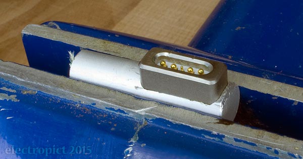
Tip: First, the connection pin assembly has to be removed from the aluminium cover. The grey rounded-rectangular thing is the magnet that holds the Tip in place; it’s glued in, but it can be removed with care and pliers. The tip must be held firmly, so a mini-vice is very handy at this stage. In the picture below you can see that this MagSafe tip has a chamfered end; this is where I filed it down to allow reinsertion of the contacts the first time I resoldered it.
With the magnet out, the contact pins can be gently pulled up and out with a fine and soft-edged pair of pliers or similar. It has to be pulled slightly back to free the retaining tab at the end before it’s pulled up.
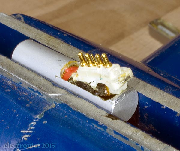
Note that the red insulator visible in this picture is something I added last time; the original had a piece of black heatshrink in roughly this position. The light-brown patches are the glue I put the magnet back with (the original glue was white). Looking at this photo, I seem to have damaged the body slightly, probably while reinserting, since photos from the time don’t show it. No functional harm though. It is not obvious from the picture how tight this is; filing the cover down helps. Once the corner of the connector assembly is out like this it’s straightforward.
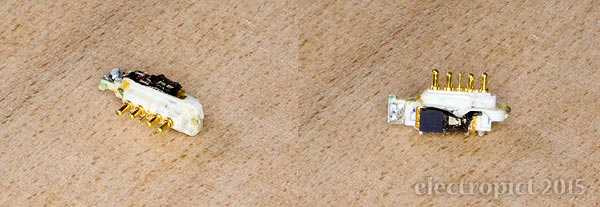
With the old wire desoldered, the thing can be seen clearly. Actually, a magnifying glass is very useful at this point. The MagSafe tip contains several components which handle some of the power switching/indication functions on MacBooks. Soldering in this area is therefore a bit more hazardous than you’d expect in an ordinary power connector. The main point to note here is that the core (supply) wire is soldered on the side with the larger chip — front in the right-hand image above, red heatshrink below. Ground is soldered on the other side (black below).
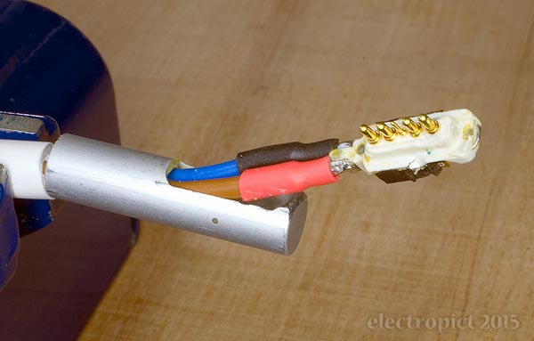
(I forgot to prepare a larger piece of heatshrink to cover the soldering, so added a piece of tape again, after this pic. You don’t want to risk contact with the tip cover.) This sheath is too large to fit into the cover, but both the insulated wires will go in, and only just pull through when soldered and heatshrinked. It’s tight enough (even with a little lubricant) that I don’t think it would work with 1mm2 wire; if that became necessary for other reasons I’d probably need to strip a few cm of ground wire and wrap it round the supply wire — coaxial once more. But we’ll see how we get on.
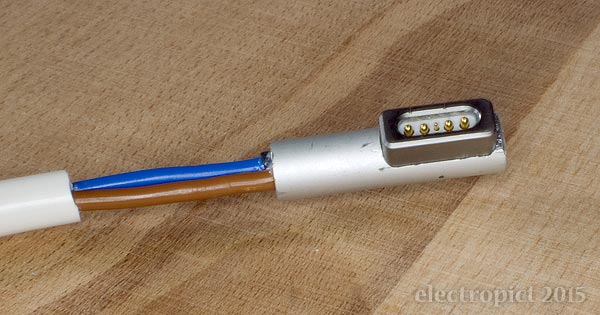
Once pulled through, I packed the gap with a modicum of self-amalgamating tape and added a heatshrink cover. It still doesn’t look great (might have been better with the next size down of heatshrink — less wrinkly), but it’s a big improvement on its previous state, or the current state of Nº4. Note that any more than about one thickness of heatshrink over the cover might prevent the plug from making proper contact; I’m not sure what the tolerances are.
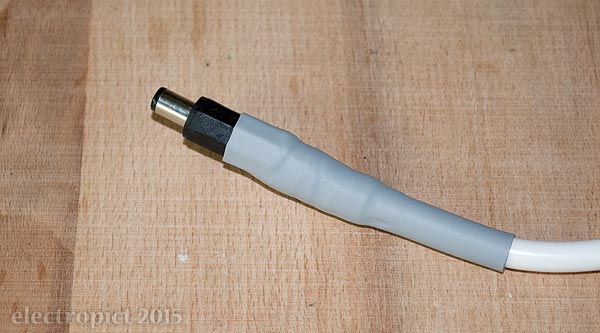
At the Adaptor end, the plug has a cover with moulded-in strain relief; this is too small for the cable so I’ve cut it off. The insulated wires stick out a little at this end too, so I’ve done the same — SA tape and heatshrink. Here I’m assuming it won’t get very hot, because there have been no previous signs of heat damage; so I didn’t try to get a high-temperature set. The cable length is a generous fathom, which should be more than enough to dissipate heat from the other end even with heavier cable. As constructed, both ends are fairly rigid and straight at the moment, but they may soften in use.
Testing is successful in the short term — it’s been plugged in for a couple of hours while I’ve been photo-processing and writing this article. Only problem is that the tip magnet came out about three paragraphs ago, so I put it back in with superglue. The tip seems cooler than it has been — not above 34° at the surface, even running Photoshop, recharging from low battery, and running an external backup over wireless ethernet simultaneously. That’s the kind of thing that brings the fans up. At the Adaptor end, the plug ground conductor hasn’t been above 28° yet. (This in about 19° ambient.)

Obviously some will see this and think the cable is awkwardly thick. True. (Thinner would be better if you can get it; this really doesn’t need 300V-rated cable.) It can be expected that it will sometimes part from the Adaptor socket. But it’s not a problem. This is a battery charger. It comes out? You stick it back in and carry on. Preferable to it exuding stickiness, turning green, and crumbling to the touch, no? But — will it last without overheating the cable or either connector? I’ll be keeping an eye on it, so in the absence of further updates, assume reasonable success.
Update, 2020-07-05
This repair survived the MacBook by a year and a half, though the cable had to be replaced twice along the way. (New cables with 2·1mm plugs became available for use with “power bricks”, and do the job fairly well, but are also prone to heat damage.) After about four and a half years though, last week the power adaptor failed. This happened during a thunderstorm even though switched off, but when I opened it I found that the heatshrink on the connections on the new socket had probably been damaged by movement of the socket, and there had been arcing. So probably not a lightning strike, just coincidence.
In the interim I did repair Nº4 as well, though I resoldered a spare-part replacement cable into it, which also failed due to heat damage at the output end after a year or two. The case wouldn’t stay together, so I taped it, and aside from the cable it’s been fine since. When the cable deteriorated I cut it back to a couple of inches from the power adaptor, and yesterday soldered a flying 2·1mm socket on it, which is much easier than opening it, making a nut, etc. Will it last? Will it need to?
Comment or Question about this page? write
Notes
- There’s also no green goo in the core at the Tip end, which implies that my earlier speculation about different plasticisers interacting may be wrong; perhaps the plasticiser from the outer sheath picked up the copper all by itself. This implies that resheathing the entire original cable would be an option . . . On the other hand, the inner insulator does seem to have expanded significantly, compared to the undamaged end. It may have absorbed extra plasticiser from outside? Or could it be a heat effect? I am still not a materials chemist, but I’d be delighted to hear from any who can shed more light. ↖
- That is, 300V/90°C-rated PVC insulators and sheath, round, stranded flex, in the CENELEC harmonised notation. In practice the cable overall is 85°-rated, which should be fine. ↖
Article text ©2015 Electropict  .
.
Click images for individual licences.