Hey! I'm ALF, from Italy. I found your great website looking for technical info about the KORG SD-400 Signal Delay. It works but the repetisiona are quite noisy (with some "air" blended with the original sound). I think it needs some fine tuning of the clock/bias. I opened it, founding 9 trimmers! I found the ones are responsible for the feedback amount. Could you provide me any schematics or give me any advice about this process? Many thanks in advance. Ciao for now! ALF
Response:
Unfortunately I don’t have any technical information about either the SD‑200 or SD‑400 apart from the user manuals (which aren’t very detailed). It took me about ten years after first getting one to find those! And since mine have been working I haven't tried adjusting any of the trimmers. I’ve been thinking of working out the circuit some day though.
A point which isn’t quite clear either here or in some of the pictures of the ARPs is what the function of the S&H external clock input is. But the later (orange) ARPs clarify that in the panel layout — the jack is an input to the S&H circuit, replacing the internal clock. Consequently it can be used to time the circuit separately while the internal clock is still triggering the transient generators.
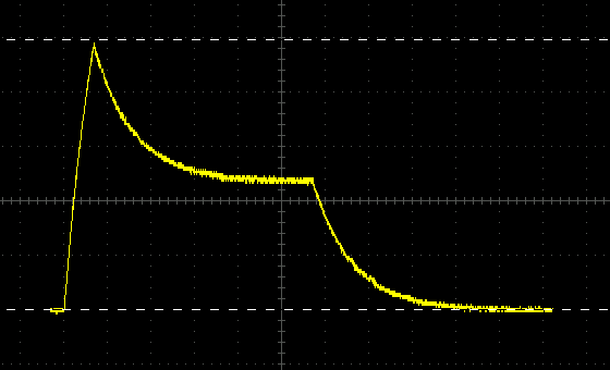
Wondering what the actual transient times were, I connected up to an oscilloscope and found that the ADSR attack is surprisingly short in proportion to the other times. This remained the case at all time settings.
Since it’s a matter of occasional confusion, even amongst people doing synth repairs for a living, I thought I might try a simple description of how divide-down polyphony in analogue instruments works.
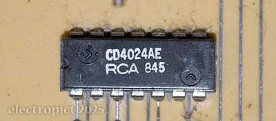
An RCA CD4024AE 7-stage frequency divider IC.
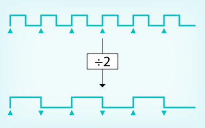
The basis of the technology is a circuit called a frequency divider. [1] This can be done differently with digital manipulation, but a typical analogue frequency divider responds to a (significant enough) change in input voltage by waiting until a similar change recurs one or more times before changing its output. The simplest and commonest division is the one-half or first suboctave, where the count is every two cycles. (A binary divider. n.b. divider circuits are often also known as counters.)
A simple binary divider triggering on the rising edge of an input waveform will switch its output state with every voltage rise (“edge”) detected. Here the falling input edges do not affect the output. Divider circuits which trigger on the falling edge can also be built.
In electronic instruments, input to dividers typically comes from an oscillator circuit. Originally, each of the notes in the top octave of divide-down instruments were generated by a separate individually tuned oscillator. The collection of oscillators this required is usually referred to as an oscillator bank.
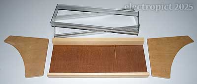
I’ve been somewhat reluctantly acquiring Eurorack modules, and recently decided that to save a bit, I’d be as well to make my own case out of an old wooden box and some bits I could buy. This didn’t work out as, once I had racks and power distribution, it became apparent that the box would need rather more modification than I’d planned. But I still wanted to rack some modules. So with a bit of rummaging around I found some scrap plywood and some aluminium sheet I took off something a few years ago. [1] Careful measuring shows that there’s a section of the sheet that should do the job, in which there’s minimal corrosion and only one hole, and I might be able to get the power socket in that space. So let’s go.
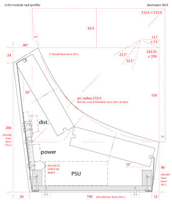
I want this case to be as compact as possible, though I don’t really know quite how this is going to fit together. I’m thinking it should be possible to fold the aluminium sheet so that it clips into the middle screw groove in the top and bottom extrusions of the (captive-nut) racks, thus avoiding any exposed metal edges. If it works, it should also be possible to fold a front and back plate over a base and then hold them in with a small number of screws.
the plan
I cut the ends out of plywood with mostly a handsaw, but using an electric jigsaw for the curve (which I drew freehand on the wood since it wasn’t trying to be circular anyway). The curve didn’t quite work out thanks to problems with the saw and clamps, but some work with a flap sander improved things. [2] The racks have countersunk ⌀3·5mm holes at either end, presumably on the basis that minimising protrusion is good. I had to buy some bolts, but couldn’t get 3·5mm so I’ve drilled the holes out to 4mm. Washers and Nylock nuts on the outside.
At this point things are a bit rough; the plywood could use a little filler but the aluminium can just be sanded and primed. Both will be painted. Black, because, black.
I’m also intending to line the wooden parts with aluminium foil. I wasn’t entirely sure but eventually decided to go with a thinner plywood scrap for the base. The front and rear support strips are another offcut of something, cut longitudinally. In practice the plywood I had for the base turned out to be a bit curved so I used a larger offcut for the rear support strip to help straighten it. The ends screw into these, making the assembly quite solid already.
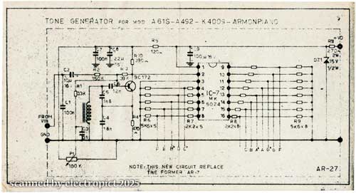
A little while ago I obtained a stack of old electronic instrument paperwork which I’ve been sorting through and am planning to scan. To start with, this is a single sheet giving what seems to be an update for the Armon “A61S-A492-K4009-ARMONPIANO”. I’m not clear whether that’s one or three separate models. The update is for a revision to a tone generator board, now AR-27. It’s undated but I’d guess late-70s. Perhaps this will be of interest to someone?
For some years I’ve been writing the Quasimidi 309’s full name as Rave-0-Lution with a zero in the middle rather than a capital O, which I’ve never liked but had somehow believed it was the original. But it struck me earlier that I can’t remember why I thought that, so I should check. And I realised that I can’t tell the difference at a glance between the O (presumably) in LUTION and the 0 (presumably) in 309 anyway, let alone decide which of them the middle character matches.
I do have a PDF of the manual but it’s a scan. As it happens I’ve had the font — Serpentine Bold Italic (PS Type 1) since about the time Quasimidi made this and it’s a good bet that they had the same font, as it was part of a Freehand package at the time if I recall. So I looked at them on screen to see if there’s a difference and couldn’t see any. So I put them one atop the other in Illustrator with colours mixed, and, yes, there’s a difference, but to be honest it’s so slight that it might as well not be there.
I never much liked this font though I probably used it for odd jobs around that time once or twice as we weren’t spoiled for choice. (Nor were Quasimidi.) But this isn’t what I’d call good design. Perhaps this package is traced from the originals, and the originals were identical? In which case I shouldn’t bother asking if it’s a zero and just use the O? I took close up shots of the middle character and the O as printed on the Q309 to compare, and put the one atop the other in Photoshop. There’s less of a difference here than between the font outlines, but still, there is a difference, and most of the differences are in the same places, which I think is a smaller difference than you’d expect from lithographic printing on brushed aluminium anyway. (In both images the majuscule O is in green and the zero (?) is in red.)
I’m not completely certain one way or the other, but I’m feeling free to write it as Rave-O-lution rather than Rave-zero-lution in future.