Getting Further In
As mentioned in the last edition, it turns out that the steel shims holding the Polivoks’ rotary switch knobs on can fall out while the knob is being inserted. [1] They could in principle fall through to the base so you might be able to pick them out and finish what you’re doing. Alternatively they could get trapped on top of the main circuit boards, where they could potentially cause shorts, and you have to get the whole thing open again and try to remove the boards to find them. If they don’t fall out visibly, you don’t know where they are. (I do understand why some resort to glue.)
So, refer to the previous getting-the-case-off process. While shim-hunting, I also want to check the probably-failed reed switch, see what’s with the 2nd octave, and see whether there’s room for improvement on the key damping to reduce playing noise. I’ve commandeered a bit of table space . . . and floorspace. This isn’t going to make me popular if I’m not done by nightfall, so let’s go.
Keyboard
State of play:
- IN4: Key damping. Consider when disassembling keyboard later.
- IN6: Dead key. Examine reed switch type when disassembling keyboard, replace.
- IN7: Functioning of second octave. Examine and test components and connections in that area.
This requires opening up the fourth and the second octave boards. There are what looks like two PCBs screwed together per octave. The outer one (in use, the lower of the two) is blank — it’s acting as a protective cover.
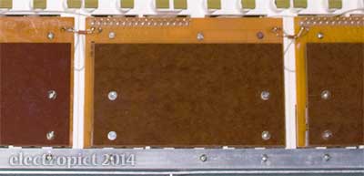
I’ll take IN7 first. The screws in these boards should be self-tappers for plastic. In this second octave two of them have been replaced with bolts, which don’t really fit the old threads. There would normally be five shorter screws in the actual circuit boards, but the two under the cover are missing here.
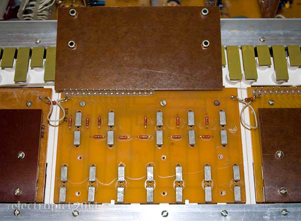
The circuit boards are joined by a soldered loop of wire and a resistor; each should be soldered to a projecting jumper wire terminal. In order to see the topside of the board, the resistors will need desoldering. (So much for speed. OK have dug out and dusted off a soldering iron.)
And it looks like I may have found the problem. This board probably has been removed, though it’s not obvious why. But when the board was replaced, one resistor (on the left in the picture) has had one tail wire-wrapped (sort of) round the terminal it’s supposed to be soldered to, losing c.5mm in the process — and hasn’t been resoldered. Which is a viable source of intermittent or variable contact. Worse, the terminal wires for both resistors were bent over, possibly touching the terminals for the connecting wires, which would be a short circuit. They were so close it looked as though they were soldered together. Fixing this may be all it needs.
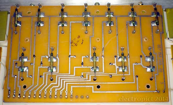
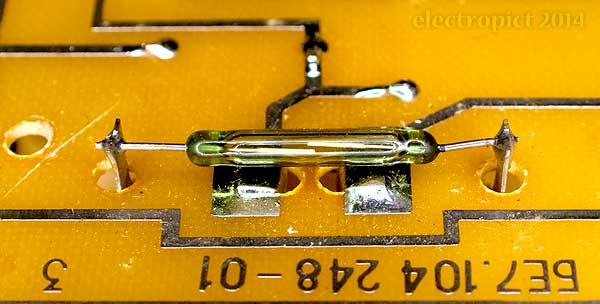
With the resistors desoldered, the board can be lifted. The top side holds the magnetic reed switches. They’re 18·5mm × 3mm tubes (about 32mm including the remainder of the leads). No obvious faults or previous work on this side.
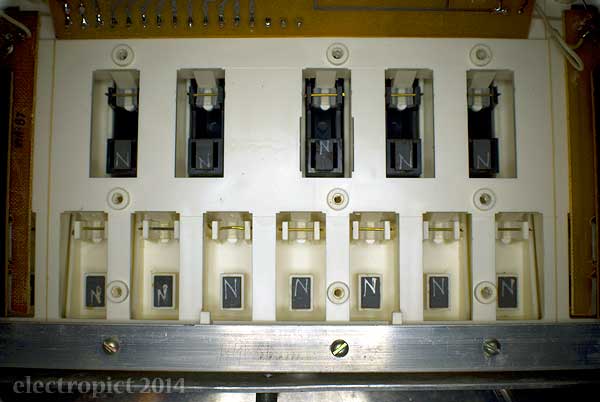
I see the keys are held on by brass retaining wires, under transparent bushes. The bushes look like a standard size, so they may be replaceable easily. That might reduce the playing noise a little as they seem a bit stiff, but the bulk of it is from the springs.
So screw back down. (These bolts don’t all fit either. Someone really went to town with losing bolts here.) And resolder. Not a lot of tail left but we have to stay clear of the connecting wire . . . done, but it’s a bit more delicate than I’d like.
On to the top octave. The process is the same, but only one resistor end to desolder. The screws are all present and original. With the board up there is nothing obvious wrong. On careful listening, the slight click audible when the other switches operate isn’t happening with the top F♯. So we can assume that one’s gone. Replacement may be straightforward, though I’ll have to wing the in/out distances.
IN4 Update: Unlikely that significant improvement can be produced by bush replacement but it would be doable.
IN6 Update: Confirmed failed magnetic reed switch. Replace.
(See below for audio test results.)
Shim Rescue
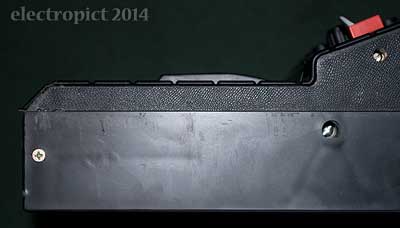
This still hasn’t got me under the main PCBs. This is where it gets awkward. The keyboard seems to need removing to allow the main circuit boards to be lifted. There are two bolts in each end panel holding it in; the front two are countersunk PH. With a bit of manoeuvring it comes out. But most of its wires are soldered on. (A case for a connector.) There’s also a ground wire bolted to the high end of the keyboard frame; removing this first makes things easier. It’s tied to the end panel with a bit of lacing cord too.
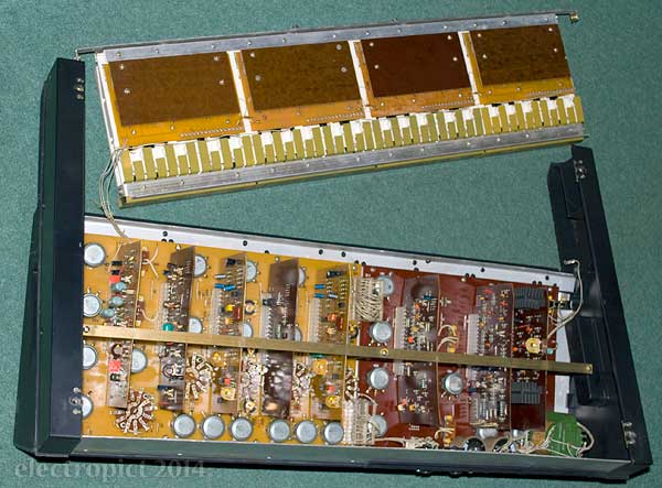
The steel strap holding all the daughterboards in place is easy to remove, but to get the boards off you also need to remove the posts it’s bolted to. They have chamfers to allow spanner grip. Turns out someone has borrowed my spanners . . .
They have promised to bring them back soon. Sooo . . . in the interim, I’ve taken photos of all the daughterboards, noted some issues but I’ll get back to that, and tidied the notes so far into near-bloggable shape.
Once it’s delivered, the posts can be removed with your 7mm open-end spanner. Even with them out and the keyboard out and all the bolts (there are 18), chances are you’re not going to get the main boards out. The Modulator/Generator/Mixer board needs desoldering from the keyboard connections. (Insert connector!) You might then be able to lift it right up, but that’s as far as you get until you desolder the audio output connections. (Insert connector!) The Power/Amplifier/Filter board is worse, as the power supply connections are soldered into it, and it is also effectively locked in by the fuse holder. You’d need to get that out. (It’s held in by a hex nut, so not impossible.) I’m not sure whether it would alternatively be removable by taking off the end panel and sliding.
As a result there is no easy access for pot replacement. And incidentally, pot cleaning. I revise my thought that they may be clean sounding because they have been cleaned. I see no way of getting contact cleaner through these pots, unless maybe with a hypodermic needle. Maybe they’re just that good . . . except, electrically. (Also, the filter modulation pot gave a crackle after reassembly.)
That being the case, I haven’t taken photos, but I have managed to look under the slightly-angled boards. There’s half a broken-off plastic rivet, but no sign of the shim. Maybe it fell out unnoticed when I was trying to shake it loose a few days ago. Since when we have vacuumed. Ah well. That which is true for motorcycles probably holds true for Polivoksen. [2] If I feel it’s really needed I’ll cut a bit out of an aluminium can.
IN9: Add connectors on wires to keyboard and main circuit boards where useful.
A Look at the Boards
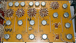
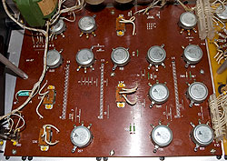
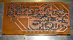
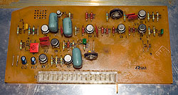
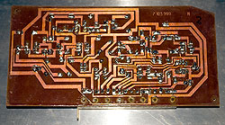
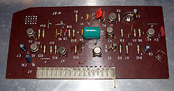
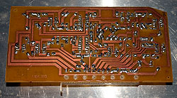
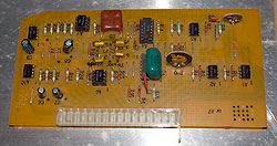
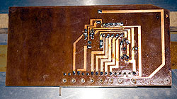
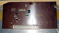
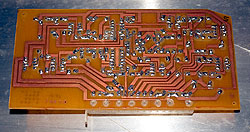
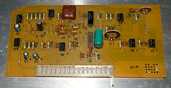
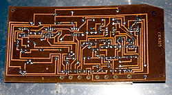
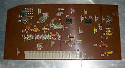
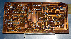
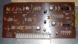
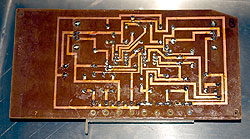
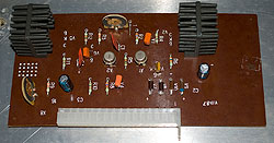
The table below gives solder and component side views of the backpanes and daughterboards. The main board numbering is the order from left to right when in playing position; Х-numbers are the connector positions on the backpanes, and also the board numbers in the schematics [3]. It may be worth reiterating that this is a 1987 Polivoks, and there are apparently some differences between some of these and the 1982 boards. Click for larger views:
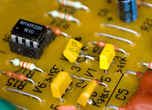
Looking at these, the major issue that struck me was that on board 3 (Generator 1), in addition to some socketed ICs which seem unlikely to be original, there is one transistor (V7 — a КТ315Б NPN) with its centre leg not connected. [4] It seems to have come unsoldered. I can’t think of a reason for this, yet it seems difficult to do by accident. On the Generator 2 board V7 is fully soldered in. In the interim I’ll try powering up again without resoldering it, and test the fixes so far.
(Out of time, everything packed away overnight.)
In the cold light of day it looks as though someone has recently replaced most or all the electrolytic capacitors. That’s good in a sense, though it implies fewer possibilities for further sound improvement. The socketed ICs on the oscillator board are also likely to be replacements. The other ICs in the synth were presumably functional when this was done. One Capacitor which doesn’t seem to have been replaced is ‘C3’, the main live/neutral smoothing cap. This is referred to as КБГ-something [5] in the schematic. I think that would be a paper-in-oil type, so wouldn’t need replacing . . . ever? But on this board there’s a K73-11 polyester cap instead, old enough that it’s almost certainly original. This may need replacing one day, if not yet.
After some time spent with the circuit diagrams and the boards, it seems the V7 transistors on both oscillator boards aren’t supposed to be connected to anything from the centre leg. Hm. The nonconnected leg is К, the collector. It does seem to have been soldered previously, like the one on Generator 2; but neither connection leads to anything on the circuit side. Looking at it again, V1 (the КТ361Г facing it) may be a replacement. Maybe the V7 desoldering and bending happened then. Resoldering would be an unnecessary hazard, so I’ll chalk that up on the board of repairs weirdness and move on.
Another point to note is that the pots are soldered on the backpanes at many different angles to match the terminals. This is presumably why the shaft chamfers are inconsistent.
Audio Test
Once it was all back together I tested the outcome of the repair. No more problem. Actually the whole thing is improved; maybe something else is making better contact now. Getting some much more sharp and chunky sounds than before. Its bell tones are great. Isn’t it irritating when you don’t know how you fixed something? However, detailed component tests would still be an idea.
There is a faint noise in the background on the headphones output which doesn’t go away when turning everything down on the mixer. I don’t recall if this was there before but it’s not mentioned in the notes. It sounds as if both oscillators are somehow feeding through the filter at a very high cutoff setting and into the amplifier — irrespective of where the actual cutoff control is. Not a huge issue as it doesn’t affect the main output.
A thing which is now quite clear — not sure if I had come to a conclusion on this before — is that the Polivoks does have filter key tracking. (i.e. the filter cutoff point rises to some extent in proportion to the pitch information from the keyboard.) Can’t put a figure on it. However, the effect is only apparent with the cutoff control in that low range where it does everything. Possibly a better pot would help with that.
IN7 Update: Resoldered potential problem connections. Outcome successful. Closed.
Next Steps
This still leaves the question of the pots. Can they — practically — be replaced with a more linear (or more accurately logarithmic) equivalent? Deciding this could use a proper test of the resistance values of the pots. But that’s probably best left till I have connectors and a reed switch to put in. And while the rotary switches don’t really need replacing for audio reasons, controls that work without extra leverage are to be preferred in my view — though some would probably say their stiffness and imprecision is part of the Polivoks charm. They’re certainly visually charming, in a mad_science sort of way, but how often do you get to see them? Still, I expect you can get used to them.
Comment or Question about this page? write
Notes
- ‘Inserted’ may be the wrong word. It is a ‘female’ knob which mounts onto a D-shaft, but it also has a projection which goes into the case around the shaft, so I need a more satisfyingly hermaphroditic term. ↖
- I’m sure someone by now will have written a Zen and the Art of Synthesiser Maintenance? (Update, 2022-01-02: Seems they hadn’t.) ↖
- Scans of the schematics are available for download on various sites. I don’t know the source, but it looks like a selection of pre-production plans. They don’t seem to be completely descriptive of the finished product. There are some divergences between the circuit diagrams and these boards. In some respects the diagrams are probably incomplete, but these boards may be a later revision. The numbers in the schematics are prefixed with ⟨Ч⟩. ↖
- Both transistors and diodes are referenced in the schematics and in the board screening with V numbers. I’m not sure what V stands for, or whether it is also used for other solid-state or semiconducting devices in Russian convention. A is used for ICs (or at least for Op Amps); not sure what that means either. According to this site, KT numbers are a series of transistors which started production in the Soviet Union in 1964 — K for silicon, T for bipolar transistor. ↖
- An unidentified character, like a ⟨U⟩ but that’s not Cyrillic, so, don’t know. (Update: it’ll be a И (I) probably.) ↖
Article text ©2014–2022 Electropict  .
.
Click images for individual licences.

