(There will be a stage 2, as I’m not currently in a position to do the whole refurb. No decent working space for soldering right now.)
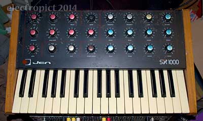
Jen#2 (not a “Jenny”, thanks) is a newly-arrived Jen Synthetone SX 1000, s/n3326, later-type keyboard, with veneer ends, in moderately poor condition.
After unpacking & supply lead check — 13A plug fuse replaced with 2A here — external condition and basic audio function were checked. Minor issues: some knobs are scratchy, some are loose. This should be resolvable, but will require checks at stage 2.
External Condition & Issues
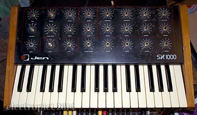
Initial exterior check showed a general problem with rust, and some cosmetic issues. Other problems:
- IN1 The bottom C key is broken. A replacement should be buyable if desired. (Though matching the yellowing here is another matter — must investigate whether the whitening gel you can make for ABS will work here).
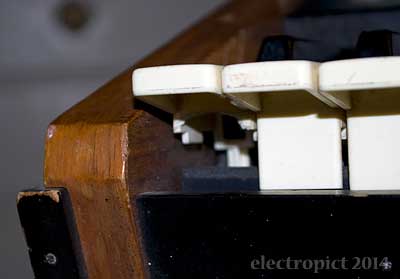
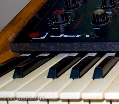
- IN2 There is an abnormally large gap (16mm at the sides, but the control panels on these instruments often bow down slightly in the middle) between the keys and the control panel. This indicates that the keyboard supports may not be in normal condition. However, the keyboard is not loose, though it flexes at front centre when the keys are pressed firmly.
- IN3 The rubber feet are not securely fixed, their screw threads having partially stripped. The rubber is tacky, as if degrading through age or exposure to something. Replacement indicated.
Audio Test Issues
- IN4 Sound cuts out entirely and scratchily with the Pulse Width knob below about 40%, possibly indicating replacement. However, with the knob at a functioning position, the same effect occurs at LFO-trough when PWM is turned high, so there is likely to be something else wrong. This will be left to stage 2.
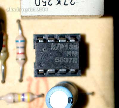
- IN5 Turning up the noise level yields the expected unpleasant pump-engine sound of the MM5837 pseudo-random noise chip. This will be left to a stage 2 upgrade (with the Electric Druid 12F675 noise chip I expect; a Zener diode-based arrangement would be possible but might require more work).
- IN6 Several keys are not making good contact, and some require pressing hard down to produce it. The unit is scarcely playable because of this. (I think this is why it was cheap.)
End-panels were wax-polished. Knobs were removed and cleaned, and the panel was wax-polished to inhibit further rust. I hypothesise that a really good upgrade would strip the panel completely, add an oxide undercoat to stop future rust, then paint & restencil. This would require accurate stencils to be made, but this might be doable with a scan whilst all the switches and pots were out of the way. I think I’ll take this scan, but have no actual plans to repaint either Jen as yet. The stencilling on Jen#2 is well out of register though, the red plate several millimetres to the left, and is also rather dim. (Does this red fade with time?)
Internal Condition & Issues
The control panel was removed and the body vacuumed out.
There is much evidence of previous work on this unit, sadly not of good quality.
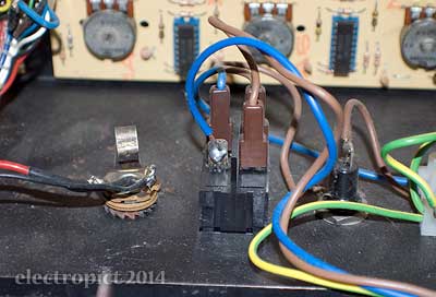
- IN7 At some point the mains neutral connector from the power switch to the transformer has been replaced by soldering. Until this is made removable, the control panel cannot be detached from the body, as the switch withdraws outwards. This makes most fixes rather too awkward to even consider in detail. So stage one is mostly about cleaning, and the next step is desoldering and replacing this connector. The present condition also leaves a 240V mains connection well exposed about 20mm from the audio output signal and ground. (Suspect this isn’t a good idea. But hey, on the other side of the switch the incoming live is exposed on both sides of the fuse carrier.)
IN8 Investigating IN2, only one (front right) of the four fixed keyboard supports still remains fixed to the keyboard bed. The rear ones have been removed entirely, and the keybed is screwed directly into the separating block which the supports would usually be fixed on. The fifth support (front centre) is missing entirely, producing the noted flexing. This is more significant than expected and really requires fixing at the earliest.
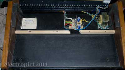
A 15mm square hardwood strip was added as a rear support, and the keybed screwed (with new pan-head screws, not countersunk) into it. A new gap was left for passage of the keyboard connector cables, thus keeping them out of the way of the transformer. This is surprisingly exact as a fit.

However, at this ‘correct’ angle, the broken left front keyboard support does not grip the keybed at all, and that corner flexes severely. The support should probably be a millimetre lower (more if adding a felt sealing strip like all the good synths have). Nevertheless, a real solution to this may need either a replacement support (but these are awkward to work round anyway), or some means of screwing directly into the keybed . . . or maybe directly onto a bolt from its other side? This remains to be resolved.
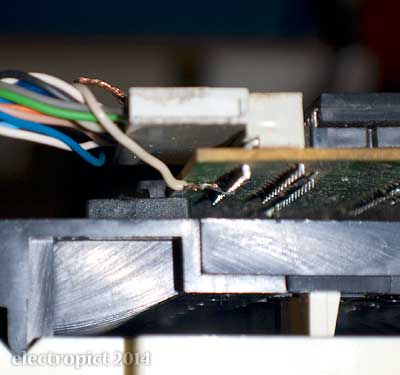
- IN9 The keyboard contact/oscillator board connector plug cannot be removed, as one of its wires has been soldered direct to the board. Presumably it came loose at some point in the past. This is a shielded wire. The shield is not connected at the keyboard end in Jen#1 either, but here the sheath appears to have been stripped back, presumably to get solderable length, and some of the shield wire has been left hanging loose, though it is not near contact with any conductors.
- IN10 The key tops had been cleaned for sale but there are significant amounts of dirt, as of past liquid spills (chocolate fondue party?), between them. The keys were removed and washed. The exposed keybed, presenting a potential biohazard, was delicately separated from the contact/oscillator board and washed. (Real improvement in the smell here.)
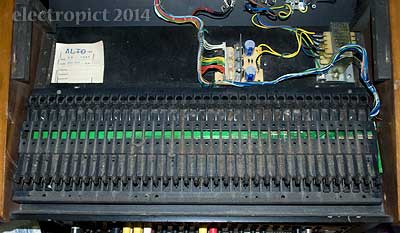
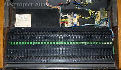
IN11 During washing it was found that the top C key was also broken — the contact spring holder strut was broken on one shoulder, and was only attached, rather flexibly, with some glue at the base. (This seems to have been solvent-based, and to have dissolved some of the original plastic; this is not ideal as you get a weaker structure.) To be going on with, the shoulder break was mended with a liberal amount of epoxy glue, and a lump of epoxy putty was added to support the side of the strut. (It would have been nice if these keys originally had some support here . . . ) This key may not last, and is a higher priority replacement than the low C key.
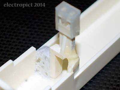
(That both ends of the keyboard have been broken, combined with the broken/missing supports, inclines me to suspect that the keybed has been carelessly removed at some point in the past. This does not seem likely to be a result of external force.)
IN12 To resolve IN6, initially the contact springs and bars were cleaned with contact cleaner. This was not found to significantly improve contacts on reassembly.
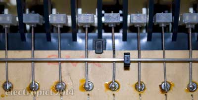
It had been noticed that many of the contact springs had been replaced (and some originals were in a poor state; one appears to have been desoldered and resoldered back to front). The replacements were not the same gauge of spring as the original — not surprising as these are hard to come by. In fact there were two different gauges of replacement springs, one thin, one very thin. This is not necessarily a critical problem, as the actual height of the spring after soldering is more determinant of contact quality than gauge; but in practice, few of the new springs were soldered at about the right height or angle. This could have been achieved by placing shims between the spring and board while soldering (e.g. damp paper). But this fix, or these fixes-plural (three attempts?) were left in a problematic state.
A perfectionist approach might involve resoldering all the affected springs to within the right tolerance; but this represents unnecessary soldering — unnecessary component hazard. It is simple to just bend the springs very slightly down at the edge of the solder, until they make good and consistent contact on keypress. (Due to the substantial variation in flexibility of the different springs this may not be the same as a consistent initial angle & height!) This took about half an hour, bending gently with a fine probe, and three rounds of retesting. The outcome is excellent.
(Caveat: while this approach works for the Jen’s single-contact arrangement, I cannot guarantee it would work with every type of contact-spring circuit.)
- IN13 While reassembling the keys it was found that several of the new contact springs were too long to allow refitting of the key; these were trimmed.
- IN14 After reassembly it was noticed that the highest B-flat key was grinding on something. This was discovered to be the front right keyboard fixing screw, which had worn into the base enough to protrude into the area of key movement. The (assumed) original 3/4″ screws on both sides were replaced with 5/8″. A washer might be an option here.
State of Play
Jen#2 is now fit to play — gently, and not whilst turned upside down, which is unlikely to occur in the near future. This will be updated.
Outstanding Issues:
IN1, IN2/8 (part), IN3, IN4, IN5, IN7, IN9, IN11
Some additional plans for stage 2 (or later):
- replace outmoded capacitors;
- replace switches with break-before-make type;
- refit missing/nonoriginal metallic caps on control knobs;
- replace power cable with C14 socket;
- improve sawtooth/square/noise gain balance;
- add CV+Gate capability (realistically this might need to be stage 3);
- other?
In its more-or-less playable state, I’ve been putting the Jen#2 through its paces; like Jen#1 it has a rather sweet and clear tone — i.e. generally sweeter than my Yamahas, and clearer than my Roland.
Comment or Question about this page? write
Article text ©2014 Electropict  .
.
Click images for individual licences.
