(Update 2017-03-29: the vermona.de and vermona-musikinstrumente.de sites seem to have gone the way of all flesh, so links to them in this article now go to the Internet Archive’s last scan of them. I don’t know if anyone else will ever host much of this information again, though vermona.de now redirects to vermona.com. . . )

Back in the DDR days, before Vermona were reinvented as a purveyor of cool synthesiser and effects gear, they (or at least the brand) had already been a purveyor of moothies, organs, amps and effects to the people for decades, so far as the people were allowed such. But in the early 1980s they came up with an all-in-one synth, simply named the Vermona Synthesizer. (References to Vermonas below are to this model unless otherwise specified.) They were manufactured from 1983 to possibly as late as 1990, though I’ve not seen a definitive end date. [1] This page begins with me getting one. And recovering a few square feet of usable working space. Up on the table with it:
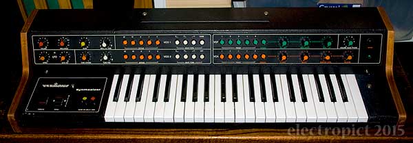
Basic Factoids
- Size:
- w900 × h170 (+5 for rubber feet) × d290 mm
- Weight:
- c. 9kg
- Construction:
- Wooden frame, veneered plywood ends, vinyl-covered aluminium shell — top and bottom, hinged.
- Keys:
- 44 (F–C)
- Voices:
- Monophonic
- Oscillators:
- 2 (each with 32′, 16′, 8′, 4′, 2′ stops [2], which can be combined).
- The oscillators have independent switchable output of c.25% pulse, square, and rising sawtooth waveforms; these can also be combined in each oscillator.
- Individual VCO level cannot be adjusted, though VCO2 can be switched off, and VCO1 can be replaced with Noise.
- There is also a Glide control (portamento/glissando) — variable and switch (for both oscillators).
- There is also a “Pitch” mod wheel.
- Noise Source:
- 1 White (switchable as an alternative to VCO 1). Noise level cannot be adjusted.
- Filter:
- 1 Low-Pass, with a manual mode with Cutoff, Resonance and Contour (= envelope level), plus 5 presets (combinable). There is also a separate “Brilliance” control which appears to raise or lower the cutoff point by around a third of the full range.
- Amplifier:
- 1, with a manual mode with direct access to the envelope, plus 5 envelope presets (combinable).
- Envelope Generators:
- 1 ADSR
- LFO:
- 1, assignable to either Oscillators (“Vibrato” mod wheel) or Filter (“VCF Mod” knob), with on/off but non-variable delay (“Delay Vibr.”) on routing to oscillators only.
- Power Supply:
- Built-in “110/117/220V”. (Update: rewireable transformer, not switchable)
- Power Usage:
- 10W
Combining means getting 2+ radio buttons to stay down simultaneously. Difficult, not reliable for performance, and it gets progressively harder with each extra button. Experimenting with this, I can get up to four registers at once; I’m not sure whether the mechanism will permit the fifth. It is possible to get all four waveform buttons down at once, so probably. I haven’t been able to get more than four presets down either. This does permit interesting combinations like VCO2 Pulse+Square+Saw+Off, and either VCF or VCA 3-presets+manual. I’ll try this out in more detail in future once some other issues are dealt with.
Electrical interfaces are (left to right):
- “Netz”: C-14 power socket,
- “Fußschweller”: mono jack pedal control,
- “Ausgang”: mono jack audio output,
- “Kopfhörer”: 270°-5-pin DIN headphone socket (mono connection across two outputs). (There is a separate headphone volume control.)

There is a mains fuse [3], mounted on the underside of the case, and two for low-voltage AC on the power regulator board.
This is s/n 270379. It has an internal stamp 870042 which may indicate assembly in 1987 — consistent with its having the later type of VCO circuit. Aside from a rearrangement of control knob colours, some replacement bolts and some dodgy cosmetic repairs, it’s unmodified.
Exterior
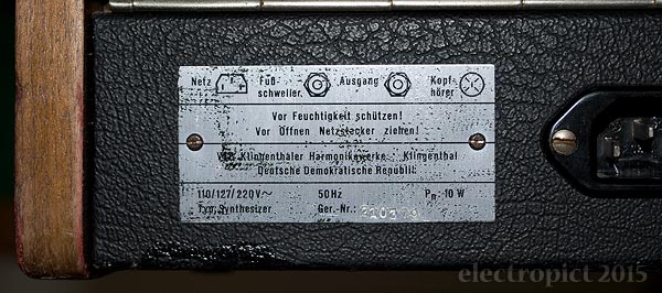
On arrival, a bit dusty. Several scrapes and dents on the vinyl, which have have been painted over, and the whole thing has been polished with something greasy. (Srsly people, don’t use wax polish on vinyl!) Some of the low-left control panel paint is freshly flaking, some has been repainted, perhaps more than once, some seems to have been touched up with black marker pen. From the internet photographic record, flaking seems to be common. Also the label plate on the back is heavily marked with a black texture, as if it’s been covered up with bitumen/cloth tape or something. Vermonas usually have a large logo plate on the back, which has been removed here, leaving only bolt holes. Seems like someone really didn’t want it identified. [4]
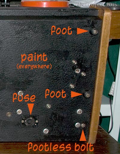
There are four rubber feet, but weirdly, one of them — on this Vermona at least — is not placed symmetrically with the others; it’s in the middle of the right side rather than at the back right corner. It’s not clear whether this is original. A foot would just fit in beside the transformer bolts, indeed, there’s a bolt in place which could hold one — and an unused bolt in the middle of the left hand end. Maybe there’s two missing? This isn’t stable, and adds to the impression of structural weakness.
The Vermona Synth is another case where some online enthusiasts have alleged that it’s built like a tank. I don’t know what it is about tanks . . . This would be a tank made of plywood and aluminium, robust enough that it wobbles under its own weight . . . The kind of tank you might make for a stage show? [5]
There are three types of control — 16 rotary knobs, 2 modulation wheels, and six sets of radio buttons (30 buttons in all, plus the power button). The pots have D-shafts, the 4·5mm × 6mm type. At first sight the knobs are some of the best ever — a very visible and tactile pointer, and they come with five insert colours. (Not enough for my taste, but it’s a start . . . ) On this Vermona, some of them look as though they’ve been in contact with a strong solvent. To the touch, they don’t make the most solid of controls. A bit wobbly. And not surprising — on investigation, they are clamped on with split rings, over-compressing the plastic — 11 out of 16 are cracked or broken. One has been glued back in previously. (Maybe that was the solvent spillage?)
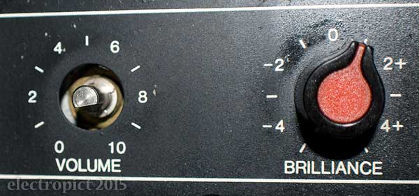
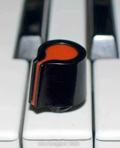
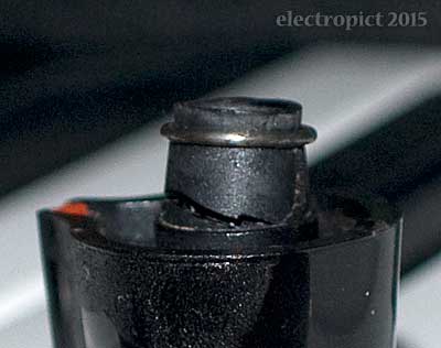
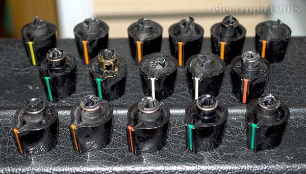
They don’t fall off in this state, but they aren’t really secure. I’m not sure if anything like these are still available, so I should consider some form of repair. It is of course immediately possible to rearrange the knobs to the original colour layout:

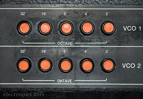
The front control panel is divided into two metal plates. Although in many respects the manufacturing is very cheap, the legend on the right plate is printed in three colours. The legend is almost entirely in English, [6] though the rear plate uses German, and on the front there is the pleasant oddity that we have VCO 1 Octave and VCO 2 Oktave stops. [7]
Some writers suggest the keyboard is difficult to play. This one feels more or less normal to me. (Normal = not touch sensitive, no aftertouch, no force feedback.) Maybe the keys land a little hard.
They are heavily scratched though — looks like someone’s been playing them while wearing steel fingerpicks or knuckledusters or something. I’ve only seen marks like these before down low on wooden doors, left by years of lonesome dogs. [8] Other than that, they’re in good shape, though uneven. Clean on top, and that’s not always true of secondhand synths.
Issues:
- IN1: Replacement or refurbishment of knobs. Non-critical.
Interior

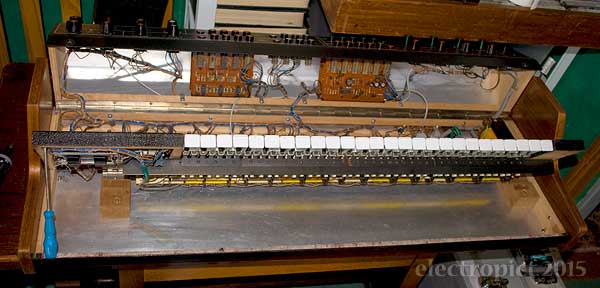
First get into it. This is unusually straightforward. The control panel is attached to the keyboard panels by a bolt on either side. With these out, the top hinges back to allow circuit access. The hinge is one piano hinge screwed in along the whole back — rather than the two or three weaker hinges you see in many more expensively built synths.
It flexes severely with the control panel open. The wooden frame is not really a frame, more edge reinforcement. The rear strip which the control panel hinges on is not actually joined to the sides. It has clearly lasted 27 years on the basis that the synthesiser which bends in the wind survives the storm, but seeing the way it moves, I’m nervously inclined to reinforcement. Especially as it tends to lean over a bit if you stand it on end. The veneered slabs are only really fixed to the base, not the back. (And the tree which bends and survives also gets to regrow and heal its cracks every year. [9])
The keyboard is held down by two more bolts. It also hinges up — but only to the point where the right upper panel fixing bracket hits the transformer. (Good that it hits something solid rather than PCBs.) With the bracket off you have full access to unscrew the hinges if required. The keyboard cannot be completely removed without desoldering wires, though.
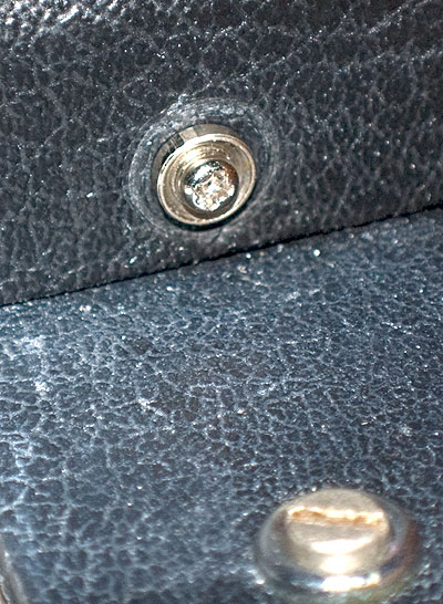
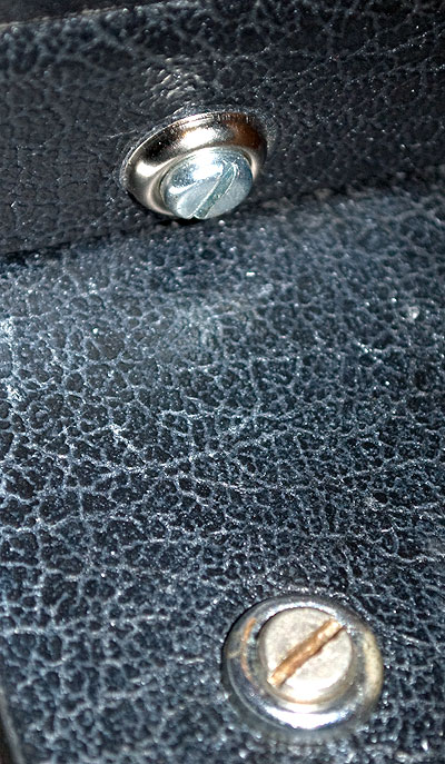
Here, the bolts that hold the control panel down seem to be replacements, and not good ones, as they don’t fit, rather mangling both threads. It’s not clear what the original threads were; about 3mm. (Update: I’ve retapped them for new M4 bolts which more or less match the other heads.)
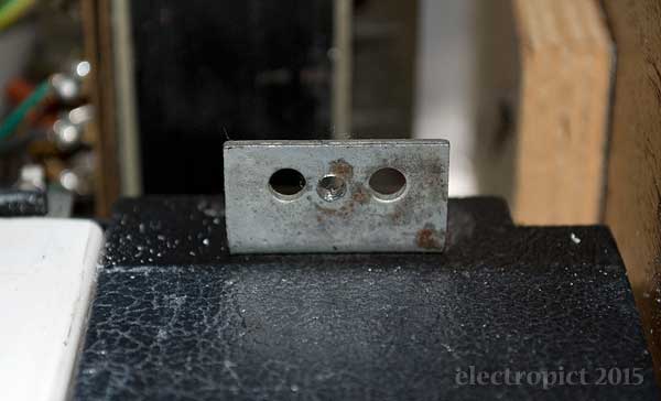
The keybed is steel, rigid and strong enough to join the panels on either side all by itself. It’s rusting a bit, which isn’t at all welcome. The contacts are j-wires, in pairs, on plated bus-bars. The wire-holders are separate from the key tops; they can be unclipped with care, allowing removal for cleaning.
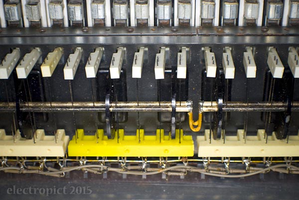
And, yes, all 88 wires are soldered in with resistors, by hand. Someone put a lot of work into that.
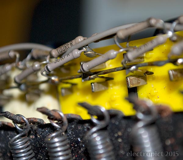
The little steel flats sticking out are wedges holding the contact wires in. It might be possible to remove the whole set at once, I’m not sure. Unlike springs, you can’t afford to bend these. [10]
Cleaning: Keyboard
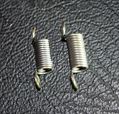
The main challenge is getting the keys off to clean underneath. First, pull the key-return springs off (try to avoid them flying all over the room). There are two different types, the black keys using slightly smaller ones — keep separate.
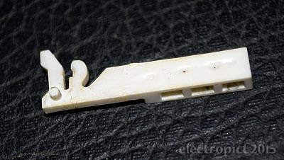
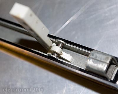
There are two types of wireholders — one (pictured above) for the C keys (not including the top C; three of these in this keyboard), and a mirror-image type for all the others. They do unclip, but I’m not content with this process. They clip onto a steel pin in the key, and take a little force to push off (using a small screwdriver/probe); it seems likely that as the plastic degrades the clips will eventually all crack in the attempt. One did this time, but still usable. Once the keys are out, the holders can be manoeuvred off the contact wires. In retrospect I think I’ll take them out as I go next time; they’re potentially hazardous to the wires while loose in place.
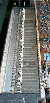
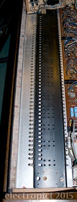
These keys are in worse condition than I’d thought; the scratches and indentations are much clearer when they’re off. Some of this may be manufacturing flaws, but I doubt it; some of it really looks like solvent spillage . . . also there are traces of black marker on some white keys and white paint on some black keys. But I suspect the scratching is where someone scraped glue off after the keys had begun to dissolve.
The keys have steel inserts, so I wouldn’t wash them in water, but they clean up fine with surgical spirit. Far from the dirtiest keys I’ve had . . . but then, this is just about the youngest synth I’ve worked on. (I’m aware that the plastic keytops can be removed, but I’m not sure it’s really safe.)
The keybed is not in bad shape; also not the dirtiest; a little rusty here and there, but a wax polish should help. It would be nice to go further, but the contact wire racks are glued and plastic-welded in place — there really seems no way of removing them short of drilling them out and reattaching with bolts. This limits cleaning options. The wires could be removed, all 88 of them, either by desoldering, or perhaps as a single net along with their resistors, but I’d hate to have to do it, let alone reinsert; and it would achieve little. So, vacuuming and polishing on top, and just a fine-tip vacuuming for the underside, I think.
The bus bars clean up electrically reasonably well; if they needed anything more than wiping with contact cleaner they could I think be desoldered and unclipped.
The bushes on the retaining brackets are fairly hard plastic, rather than rubber. The keys themselves have spongy damping inserts — a bit aged here, but extremely difficult to replace cleanly. Not this time, anyway. The brackets are mild steel, and can be bent by finger pressure to adjust final key height.
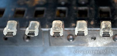
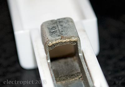
In reassembly, it seems that clipping the wireholders back into the keys is harder than getting them off, particularly on the black keys. A little plastic-safe lubricant helps, and should ease future removals. The wireholders have to be put back on the wires before mounting the keys. (The photo below is for testing and demonstration.) The wires go into the lower two holes.
Circuitry
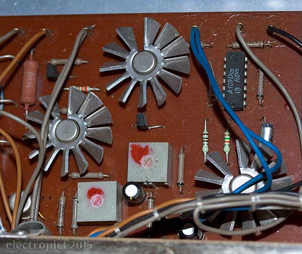
The power boards in Vermonas typically have three heatsinks. An appreciable amount of heat rises above them. Even with them, the components they’re on reach up to 33°C in use. [11] Their surfaces, and therefore the heatsinks, have different potentials, so there’s up to 31V from heatsink to heatsink and from the heatsinks to the component tails beneath them. So they must not be allowed to slide down. Unfortunately there are no identifying marks on these components, and their legs are hidden by insulation. (Update 2015-07-14: while checking components under one of the heatsinks a couple of days ago, under a different light colour, I noticed what looked like faint markings. Careful examination with a strong torch shows these to be BC211 transistors. The other metal-packaged object beside them is an MAA723 voltage regulator.)
The wiring has had a pretty good lacing job. Which keeps things neat, helps you see what you’re doing — as long as you can distinguish the wires . . . But here, colour coding is not really used. I thought it might be black for ground, but nope. In at least one case there’s voltage between ground and a black wire on one of the boards . . . There’s black, brown, blue, grey . . . and also green on the AC side. Maybe it was a cost issue; but the restricted colour range doesn’t help much in laced bundles. As no-one seems to have any circuit diagrams available it looks like we’re testing and labelling everything before we’re done . . . [12] (Update 2016-04-08: Circuit plans are now available at vermona.com.)
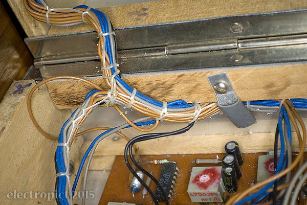
At the same time, at least the circuits are fairly simple. These are not the most densely populated boards I’ve worked on . . . (A nice thing about the Vermona design: not only small, discrete boards, but most of them are easily accessed. You can get probes on them still in place — and get them out for the camera easily.) Unfortunately they don’t have any screened component numbers or descriptions.
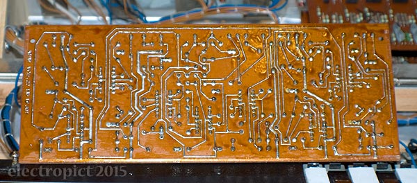
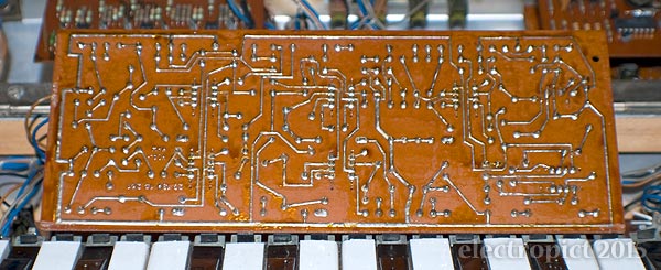
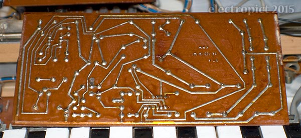
One laced bundle — 18 wires — goes to the keyboard, which it’s going to be handy to make removable, so I might just cut it and put a connector in somewhere.
Another nice thing is that the pots are all exposed under the panel, making access for cleaning quite simple. I notice in the picture below that the sustain pot is wired with two blacks — maybe the source of voltage on a black wire. In fact . . . the ADSR pots are all wired with the same colour on both sides . . . ? Hm. Good to know.
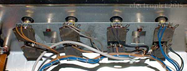
The boards and mounts on the front panel are all bolted on — with 5·5mm hex nuts. That’s awkward. And there’s not really room to get a normal ¼″ socket in to some of the nuts, so you need a spanner or a nut driver. This is the first time I’ve had a use for my 5·5mm nut driver, and it turns out it’s too long to get into the upper bolts. A small spanner might do for most of them; but even that isn’t going to work on the power switch right nut. Maybe a c.60mm deep drive socket? Or it might take a box or crowfoot spanner?
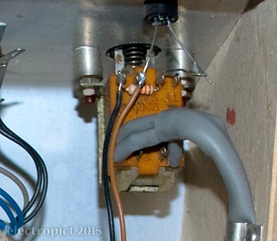
Some Components
According to CHD, who do a MIDI retrofit for it, there were at least two versions of the Vermona, with component differences in the VCO board at least. This is the later version, with A109D Op Amps. This Vermona also uses A109Ds on other boards, but I don’t know whether that applies to the earlier version or not.
Integrated Circuits:
A109D Op Amp (lots of them), D100D Quad NAND Gate, D121D Flip Flop. These are DDR equivalents of common international components. Individual chips do have different Rn and Pn numbers; I don’t know whether that’s significant.
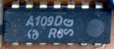
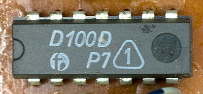
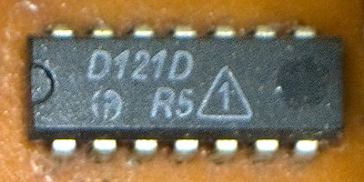
None of the ICs are socketed.
Capacitors:
There’s an RFT-brand AC transient suppressor on the incoming supply. It’s linked from its ground terminal to the case, the regulator board, and the transformer through a large ceramic disc. It’s leaked. I don’t know what it’s leaked. I don’t like it.
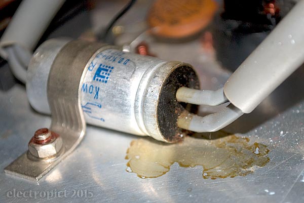
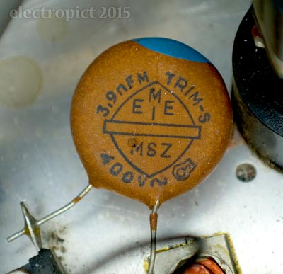
Both these and the transformer are mounted on the aluminium sheet which is the underside of the synth. (An excellent reason for having a flight case.) RFT seems to be a DDR make, but I’m not seeing any direct replacements. [13]
Apart from some of the larger caps, most components aren’t visibly that bad compared with other synths I’ve had. Of course, it’s a decade younger than most synths built out of discrete components.
Issues
- IN2: Structural weakness. Consider strengthening rear corners with angle brackets. Non-critical.
- IN3: Replace Control Panel fixing bolts. DONE — CLOSED
- IN4: Find replacement for leaky transient suppressor.
Electrical Function
Switch on, and, right, a challenge! Power supply seems reasonable — though I’ve not found a 21V circuit in a synth before (pending a full circuit analysis this seems to be solely for the power indicator LED; it stands a chance of being a nominal 24V supply). But otherwise, I’ve never had a synth in such poor functional state. To the point where it’s not really clear what some of the controls are intended to do. Likely to need recapping, new pots, and first, contact cleaning. Also, retuning.
Issues
- IN5: The Pitch control wheel seems to have no effect at all.
- IN6: The vibrato control . . . well, it might work better if the LFO was working, but mostly it just lowers the pitch. Then it affects the LFO when high (see below).
- IN7: The LFO doesn’t function at all unless Vibrato is turned high, and then it starts fast, and actually slows if you turn it up — until about half-way, when it disappears again. (Update: Now not working at all. Major fault is probably the Speed pot. Replacement required.)
- IN8: Very difficult to tune. The trim pots have been rather abused, and some of them seem to jump about a bit, but though replacement might be a good thing, I suspect there are other component issues affecting this. Consider replacement once other functions are corrected.
As a non-specific issue, it also tends to produce random pitch and filtering shifts (even after being on and warm for hours); this may be sortable with pot cleaning, but may indicate a more significant problem.
Aside from which, it’s notable that the output on this Vermona is surprisingly loud. Not sure if that’s normal. But I’ve been using it at about mark 4 (out of 10), which comes in about the same as mark 7 or 8 on most of my other synths.
Cleaning: Control Pots
In spite of restricted work space it was possible to properly clean the pots. The key contacts are also accessible, if awkward.
The LFO Speed pot emitted a chunk of something during cleaning. Not quite sure what. And afterwards it ceased to function completely. Which implies that the pot is the problem, and that’s an easier fix than a board repair, so, good. Probably.
The VCF Contour and Resonance pots also need replacing. The other pots are much less scratchy now, but some have significant dropouts. Maybe all 18 . . .
So IN9 is: generally poor condition of control pots. Consider across the board replacement. LFO Speed, VCF Contour and Resonance required.
Audio Function
Assuming it’s possible to tell from the current state,
- key priority is High;
- trigger mode is Single;
- there is no key tracking;
- the filter resonance does not reach self-oscillation.
I’m not yet clear what the Brilliance control really does, though it does seem to be a Low-Pass control, altering the VCF cutoff point. Maybe the intent is to have a filter control for the left hand too. (Admittedly, it seems handy like that.) More likely, it’s there to allow cutoff point adjustment when using either manual or preset VCF settings.
I’m not clear either how the Delay-Vibrato switch works, but tentatively it seems likely to be a simple slew limit which brings the effect in slowly (in slur mode, it doesn’t affect secondary keypresses), rather than a complete delay. It doesn’t seem to affect VCF Modulation. As with the Vibrato, it cannot be assigned to only one oscillator.
Given the operational faults, it’s not realistic to assess audio quality yet. However, while it will probably be very limited compared with every other synth I’ve used, in this state the Vermona does seem to produce some startlingly good bell and brassy tones. And some rather classic ’70s organ sounds to go with its appearance. Hopefully all these will still be there when I get it working properly.
I am just beginning to suspect that when people describe the Vermona as having an ‘evil’ tone etc., what they are really saying is, ‘it’s randomly making noises I didn’t expect’ — which this one certainly is — and actually the circuits are shot. (And/or the gain is so high they’re overdriving their amps.) The basic character of the sound here is surprisingly warm. But we’ll see what happens when there’s a functional filter and LFO.
Future
It’s going to be a bit of a project, isn’t it? The first priority looks like obtaining or just drawing full circuit diagrams; that’s going to be necessary for working out many of the later details. Replacement components are clearly necessary. Some simple replacements should just proceed.
Possible Mods
- Jack socket for headphones? I hardly think it’s worth it. I’d like to test the headphone volume pot as audio, but that can be done with leads.
- MIDI (because the card is available . . . ) and CV connections.
This post has been updated in Some Pipe and Register Measurements, and Vermona Synth Boards.
Comment or Question about this page? write
Notes
- The history is a lot more complex and I know little about it. Briefly, Vermona was incorporated into the state musical instruments company KHW during the DDR period, and is now a brand owned by HDB Electronic GmbH. (‘KHW’ can be seen on the PCBs. It turns up on the rear plate in full: VEB Klingenthaler Harmonikawerke) The new Vermona have also, while I’ve been compiling this post, announced a new “Vermona Synthesizer ’14”, which is described as ‘extending the original’, to be released in Spring 2015. ↖
- Looking at it on a mostly English-labelled German synth . . . I don’t know. Are feet and Prime an English-language convention? Since this convention stems from pipe organs, were pipe organs all over Europe described in feet, in the past? Organs predate the metric system, but there were other older systems. Have there ever been organs (or synths) described in cm? Or, were the Prime (′″) marks used with other pre-metric measurements? A quick shuftie at Wikipedia gives no answers to this. I may get back to it. ↖
- This one seems to be a normal-speed 1·6A, which is curiously large for a 10W device. May not be original. 0·16A would be more likely, though I’d think that a little low. There wasn’t a convention of placing the decimal comma after the first digit? ↖
- I suspect the cosmetic effort/cover up was partly for the cameras. It was used in some videos by its previous owner(s), in which it has no identifying marks on the rear. Quick reviews . . . Save You: music OK, video approaching the misogynist; Under the Moon: music not half bad — catchy even, when listened to without video, and the video’s an improvement on the last one, though it distracts from the music more as a result. But in general, please connect synths’ audio-outs if you want it to look like you’re playing them, yes even in the forest at night . . . or get one of these little hand-held things with speakers, like Trio had. (If a synth is disconnected in the forest, does it make a sound, whether there’s anyone there to hear it or not?) ↖
Has anyone ever made a tank for a stage show?
. . . now I remember it, yes. This one at least. (Full article here.) Probably not the sort of tank the enthusiasts were thinking of. Now try to envisage a synth built along these lines. Bear in mind CV-operated lighting controllers. It may not need space on top for dancers, but it’s probably doable . . . indeed if you really wanted to build a synth along these lines I suppose the control mechanism could be continuously scanned dance movements? ↖
- Which seems odd, since the DDR wasn’t known for official love of the nearby Anglophone presence, and the main external market for this was the Warsaw Pact zone — in much of which, German used to be widely spoken and English wasn’t. But no. Is English just the international language of synthesis? Maybe once you include all the adopted Italian terms . . . though ‘Vibrato’ is the only example here. (I suppose ‘brilliance’ and ‘resonance’ are French, sort of?) USSR-made synths mostly used Russian and Cyrillic, so I don’t know . . . Japanese-made synths tend to be English-labelled, but they’re aimed largely at the English-language market. Maybe in much of Eastern Europe, English was the only acceptable compromise between Russian and German . . . if so, that tells me something about the Cold War I didn’t know at the time. But then, if only a thousand were made, and only 700 exported, it’s not a significant market anyway. Headscratching to no avail. ↖
- Deliberate? Presumably. If I ever build a synth of my own it will be as macaronic as I can make it. And will feature at least three scripts.
. . . In fact, though it’s unlikely to be my kind of thing, it would be interesting to see a synth labelled in hieroglyphics. Mayan or Egyptian? ↖
Consider that. I have considered it and come up blank. This is a synthesiser. Yer not gettin’ in, don’t even ask.
. . . Or, actually, having seen the Apsürde videos, and another on YouTube, in which Vermonas are supposedly being played with gloves on, I can’t help but think of that old Paul Outerbridge photo of the nude model prodding herself with with meatpacking gloves . . . and a later take on it with kitchen gloves and icing nozzles (can’t find that on the web) . . . that might leave marks like these . . .
. . . which sort of raises the question, if manufacturers are, as seems to be suggested, close to producing artificial-intelligent and convincingly humanoid robots capable of learning complex behaviours like dancing, how much more difficult (and perhaps grotesque) would it be to have a humanoid, walking, talking, singing synth, played by touch? I mean, synth controllers built into your clothes are decades old now. The tech is probably in existence as I write, in primitive form, if it could be marketed. An attractive thing about this option is that the synths could actually dance around on-stage with the musicians (keytars never did it for me) . . . or on the tank, of course.
But never mind ‘humanoid’ — let the synths have the claws! The catgirl synth may be fully realisable . . . but a crocodiloid might be easier to play (more knoblike bits) . . . zebra’s obvious . . . giant tortoise drum machine . . . ? A jardin zoösynthetique beckons! Make mine a stegosaurus.
The only question is whether it would be easier to implant a controller direct in your own damn flesh. Puny human. ↖
- Not yet an option with synthesisers, though it may be one day. We could start with self-healing PCBs. At that point you might as well just graft them into a tree . . . OK this isn’t going to be so convenient for touring. Though big pots with castors would make it doable. Or, put a motor on it, and a P.A. A calliope for the modern age. ↖
- Conversely, this ‘Studio Dreadful’ picture of a Vermona synth keybed shows bright metal, perhaps aluminium, and circuit boards rather than hand-wiring, and contact springs rather than wires, and the whole thing seems to screw together. This is so different from every previous KHW keyboard that I’d suspect it was a retrofit — but it does seem very similar to the keyboard of the Tiracon 6V, which was also manufactured by KHW from 1988, so maybe some were built like this towards the end? ↖
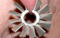 I have seen a picture of the insides of a Vermona without the heatsinks. Maybe there was a revision with cooler-running components . . . ? Or perhaps someone walked off with them. They’re pretty enough to wear as earrings . . . ↖
- Diagrams and the original manual are supposedly available at vermona.de but I’m not clear how. Maybe you need to be able to see Flash content. (Update 2016-04-08: Circuit plans are now available at vermona.com.) ↖
- Though there are people selling what looks like old stock on eBay. I think I’d like something new on the whole. ↖
Article text ©2015–2017 Electropict  .
.
Click images for individual licences.
